
To start coding with Arduino for robotics, begin with an Arduino Uno, learn basic C++ through small sketches, and build up to controlling a motor with a driver before adding sensors. That step-by-step path is easier to debug—and much more satisfying—than wiring every component together and hoping the robot understands your intentions.
The first time we tested a two-wheel rover, it promptly spun in a circle. The culprit wasn’t a sophisticated software bug: the motors were turning in opposite directions. Testing each motor separately would have caught it in minutes. That’s the secret to learning Arduino robotics: make one thing work, understand why, then add the next.
You don’t need to be an electronics expert or a C++ wizard to begin. A little coding, careful wiring, and a habit of testing one change at a time will take you from a blinking LED to a robot that can move, sense, and respond.
Key Takeaways
- Start with the basics: Upload a blinking LED sketch, then learn
setup(),loop(), variables, and simple conditions. - Build in stages: Test motors before adding sensors; test sensors before combining them with robot behavior.
- Use a motor driver: Never power drive motors directly from Arduino I/O pins.
- Check power and wiring: Match the board, driver, motors, and battery, and connect a shared ground where required.
- Make debugging part of the build: Use the Serial Monitor, test one component at a time, and change one thing at a time.
- Grow your skills with projects: Move from a basic rover to obstacle avoidance, line following, encoders, or a robot arm.
Table of Contents
- ⚡️ Quick Tips and Facts: Start Arduino Robotics the Smart Way
- 🧭 What Does It Mean to Code a Robot with Arduino?
- Arduino, microcontrollers, and robot controllers explained
- What you can build with beginner Arduino code
- 🕰️ From Maker Boards to Arduino Robotics: A Brief History
- 🧰 What You Need to Start Coding Arduino Robots
- Choosing an Arduino board: Uno, Nano, or another model
- Essential robotics parts: chassis, motors, wheels, and motor drivers
- Beginer-friendly sensors, wires, batteries, and tools
- Arduino IDE, Arduino Cloud, and other coding tools
- 🛒 How to Choose Your First Arduino Robotics Project
- Start with LEDs, a servo, or a simple two-wheel robot?
- Matching project difficulty to your coding experience
- 🔧 Set Up Your Arduino Board and Development Environment
- Install the Arduino IDE and connect your board
- Select the board and port, then upload a test sketch
- Set up libraries and keep your project files organized
- 🧠 Arduino Coding Basics for Robotics Beginners
- Understand sketches, setup(), and loop()
- Variables, data types, and constants
- Digital and analog inputs and outputs
- If statements, loops, and functions for robot behavior
- Using millis() for responsive, non-blocking robot code
- 💡 Your First Arduino Sketch: Blink an LED and Read a Sensor
- Upload a built-in LED blink program
- Read sensor values with the Serial Monitor
- Common upload errors and what they mean
- 🔌 Wire Arduino Robotics Circuits Safely
- Read a wiring diagram and use a breadboard
- Connect sensors without damaging Arduino pins
- Why motors need a driver instead of direct Arduino power
- Battery choice, voltage, current, and a shared ground
- ⚙️ Control Robot Motors, Servos, and Speed
- Choose an H-bridge motor driver for DC motors
- Set motor direction and speed with PWM
- Position a servo motor with Arduino code
- Avoid brownouts, overheating, and motor noise
- 📡 Add Sensors and Give Your Robot Useful Awareness
- Measure distance with an ultrasonic sensor
- Detect a line with infrared sensors
- Use bump switches, light sensors, and encoders
- Combine sensor readings into reliable decisions
- 🏁 Build a Line-Following Arduino Robot
- Asemble the chassis and connect the electronics
- Write the line-following logic
- Calibrate sensors and tune motor speed
- Improve turns, cornering, and track consistency
- 🧪 Test, Debug, and Improve Your Arduino Robot
- Use Serial prints and simple test sketches
- Check wiring, pin numbers, libraries, and power
- Diagnose a robot that moves unpredictably
- Make one change at a time and record results
- 🛡️ Arduino Robotics Safety and Best Practices
- Protect boards and components from shorts
- Handle batteries and moving parts responsibly
- Build tidy, maintainable wiring and code
- 🚀 What to Learn After Your First Arduino Robot
- Bluetooth and Wi-Fi robot control
- Encoders, PID control, and precise movement
- Arduino robotics with Raspberry Pi and ROS
- Project ideas to build your skills
- 🎯 Key Takeaways for Getting Started with Arduino Robotics
- Conclusion
- Recommended Links
- FAQ
- Do I need to know C++ before starting Arduino robotics?
- Which Arduino board is best for a first robot?
- Can I connect a DC motor directly to an Arduino?
- What is the easiest Arduino robot to build?
- How do I power an Arduino robot safely?
- Why won’t my Arduino sketch upload?
- How long does it take to learn Arduino robotics?
- Reference Links
⚡️ Quick Tips and Facts: Start Arduino Robotics the Smart Way
If you want to start with Arduino for robotics, keep the first goal wonderfully small: make a robot move forward, stop, and turn. Add sensors only after you can control the motors reliably. That order saves debugging time—and prevents a loose wire, a weak battery, and an ambitious obstacle-avoiding algorithm from all demanding attention at once.
| Quick fact | What it means for your first robot |
|---|---|
| Arduino sketches use a form of C/C++ | Learn a small set of programming building blocks; you don’t need to master all of C++ first. See the Arduino language reference. |
setup() runs once; loop() repeats |
Initialize pins and serial communication in setup(), then run the robot’s behavior in loop(). |
| A DC motor needs a motor driver | Don’t power drive motors directly from an Arduino pin. The Arduino Uno R3 documentation lists a 20 mA DC current limit per I/O pin. |
| A shared ground matters | Connect Arduino ground and motor-driver ground so control signals have a common electrical reference. |
delay() pauses your program |
It’s useful for a simple first test, but millis() is better when the robot needs to read sensors while moving. |
| Start with one behavior at a time | Test movement, then sensing, then decision-making. A robot assembled all at once is a debugging detective story with too many suspects. |
Our beginner recipe: Arduino Uno R3 or compatible board + two geared DC motors + a 2WD chassis + a suitable H-bridge driver + a separate motor power source. Add an ultrasonic or line sensor once the basic drive works.
✅ Do: disconnect power before changing wiring, test motors with the wheels lifted, and check the motor driver’s voltage and current ratings.
❌ Don’t: assume the Arduino’s USB connection or 5 V pin can safely run your drive motors.
The opening video, “Arduino is easy, actually” by Robonyx, offers a quick introduction if you’d rather see the basics explained before setting up your board.
🧭 What Does It Mean to Code a Robot with Arduino?
Coding an Arduino robot means writing instructions that connect inputs to outputs. A sensor provides information; your sketch interprets it; an actuator responds.
For example:
- An ultrasonic sensor reports that an obstacle is nearby.
- The Arduino compares the reading with a distance threshold.
- The Arduino tells a motor driver to stop one wheel and turn the other.
- The robot changes direction.
That simple loop is the foundation of more sophisticated robotics. As Niryo explains in its Arduino robotics guide, Arduino gives learners practical building blocks for motor control, sensors, and basic logic. For an introduction to robotic sensors, it helps to think of the Arduino as the robot’s small, fast decision-maker—not as a humanlike brain.
Arduino, microcontrollers, and robot controllers explained
An Arduino board is built around a microcontroller: a compact computer designed to read inputs and control outputs. It runs your sketch directly and is well suited to repeated, predictable tasks such as reading a switch or adjusting motor speed.
| Part | What it does | Beginner-friendly example |
|---|---|---|
| Microcontroller board | Runs the program and reads or controls pins | Arduino Uno R3 |
| Sensor | Measures something about the surroundings | HC-SR04 ultrasonic sensor |
| Motor driver | Provides the electrical switching needed to control motors | TB6612FNG breakout board |
| Actuator | Creates movement or another physical response | DC gear motor or servo |
| Power supply | Provides suitable energy to the board and motors | USB for setup; separate battery supply for motors |
An Arduino is not usually a replacement for a desktop computer. It shines at real-time input/output and small calculations, while tasks like computer vision and heavy AI are generally better handled by a Raspberry Pi or another computer. The two can work together: the computer can process complex information, while the Arduino handles timely motor and sensor control.
What you can build with beginner Arduino code
Early projects teach skills you’ll reuse everywhere:
- Blinking LED: outputs, timing, and uploading a sketch.
- Servo sweep: actuator control and simple functions.
- Obstacle-avoiding rover: sensor readings and decision logic.
- Line-following robot: calibration and motor-speed adjustment.
- Robot arm: servo positioning and movement sequences.
A line follower can be a satisfying early robot, but it introduces several moving parts at once: motor wiring, sensor calibration, and steering behavior. We recommend first making a two-wheel robot drive straight. Once it does, line following becomes a manageable upgrade rather than a mystery machine.
🕰️ From Maker Boards to Arduino Robotics: A Brief History
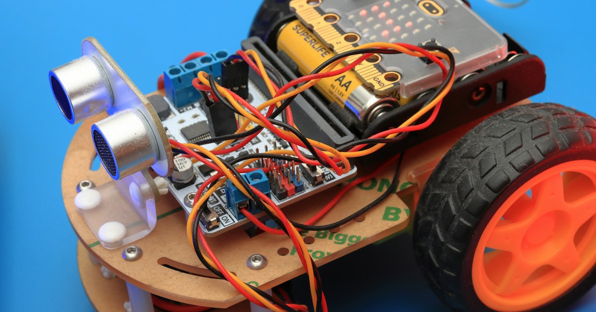
Arduino grew out of the open-source maker movement, where accessible electronics and shared designs helped more people experiment with interactive hardware. Arduino’s official documentation now covers boards, programming, and built-in examples, while communities such as Arduino Forum let makers compare notes and troubleshoot projects.
The practical effect for robotics learners is simple: you don’t have to invent every circuit or library from scratch. You can learn from example sketches, adapt proven designs, and spend more time asking useful questions such as, “Why does this robot ver left when both motors have the same PWM value?”
🧰 What You Need to Start Coding Arduino Robots
A first build doesn’t need a workshop full of tools. It does need compatible parts. Check the motor driver’s operating voltage and current rating, the board’s logic voltage, and the battery’s output before connecting anything.
Choosing an Arduino board: Uno, Nano, or another model
| Board | Best suited to | Helpful points | Considerations |
|---|---|---|---|
| Arduino Uno R3 | First circuits and beginner robots | Familiar layout, many tutorials, easy to prototype | Larger than a Nano; fewer pins than a Mega |
| Arduino Nano | Compact builds and breadboards | Small form factor; convenient for embedded projects | Pin spacing and USB-to-serial details vary by version |
| Arduino Mega 2560 Rev3 | Builds needing many pins | More I/O for multiple sensors and actuators | Larger than most beginner rover projects require |
| Arduino Nano ESP32 | Projects needing wireless features | Wi-Fi and Bluetooth capabilities | Different pin behavior and setup from classic Uno examples |
Our recommendation: begin with an Uno R3 or an Uno-compatible board if you’re following beginner tutorials. The board’s pin labels, examples, and learning resources are widely familiar. Choose a Nano when compact size matters, a Mega when you truly need more pins, or an ESP32-based board when wireless communication is part of the project.
Avoid selecting a board just because it has the biggest feature list. A beginner robot usually gets more value from a clear pin map and a compatible motor driver than from extra processing power.
Essential robotics parts: chassis, motors, wheels, and motor drivers
For a basic rover, gather:
- 2WD chassis, two wheels, and a caster wheel
- Two geared DC motors with compatible mounting
- A motor driver, such as a suitable TB6612FNG breakout or an L298N module
- Arduino board and USB data cable
- Battery pack chosen for the motors and driver
- Jumper wires and, optionally, a breadboard
- Optional sensor, added after basic movement works
Geared motors turn more slowly than many bare motors but generally provide more useful wheel torque. Servos are better for controlled angular movement, such as turning a sensor or positioning an arm joint. Steppers are useful when a project needs commanded incremental movement, but their position can be lost if the motor stalls and no feedback system detects it.
The TB6612FNG is often favored for compact battery-powered robots because it can be more efficient than older driver designs, but the exact board and motor specifications matter. An L298N remains common in learning kits, though its driver design can dissipate more power as heat. Compare the datasheets and breakout-board details rather than choosing by name alone.
Beginer-friendly sensors, wires, batteries, and tools
| Component | Common use | What to check |
|---|---|---|
| HC-SR04 ultrasonic sensor | Approximate distance measurement | Supply voltage, echo voltage, mounting, and target surface |
| IR reflectance sensor | Line detection | Sensor type, output format, lighting, and sensor height |
| Pushbutton or bumper switch | Contact detection | Pull-up or pull-down configuration and secure mounting |
| Wheel encoder | Speed or rotation measurement | Encoder voltage, pulse count, and interrupt support |
| Multimeter | Voltage and continuity checks | Correct measurement mode and safe probe use |
| Battery pack | Powers motors, and sometimes the controller | Chemistry, voltage, current capability, and safe charging |
A breadboard is excellent for early experiments but can loosen under vibration. Once the wiring works, secure connections with appropriate connectors or move to a sturdier soldered protyping board.
For more sensor ideas and explanations, browse our robotic sensors guides. A sensor’s advertised range is not a guarantee of equally reliable readings in every room; surface shape, lighting, mounting, and electrical noise all influence results.
Arduino IDE, Arduino Cloud, and other coding tools
The simplest place to start is the free Arduino IDE. It lets you write sketches, compile them, upload them to a board, and inspect serial output. The Arduino IDE guide explains installation and setup.
Other options include:
- Arduino Cloud Editor: browser-based editing and board management; check board and account compatibility.
- PlatformIO for Visual Studio Code: a capable environment for larger projects, but with more setup and concepts.
- Tinkercad Circuits: browser-based circuit simulation that can help you test basic Arduino ideas before wiring physical parts.
For your first sketch, use the Arduino IDE. Save PlatformIO for when you want structured project management or already work comfortably in VS Code. More tools are not automatically more progress.
🛒 How to Choose Your First Arduino Robotics Project
Choose a project that teaches one new skill at a time. If you’ve never uploaded a sketch, begin with an LED. If you already know the IDE, try a servo or motor-driver test. If you can control two motors confidently, sensors are a sensible next step.
Start with LEDs, a servo, or a simple two-wheel robot?
| Starting point | You’ll learn | Good fit if… |
|---|---|---|
| Built-in LED blink | Sketch structure, pin setup, upload process | You’re new to Arduino |
| Servo movement | Libraries, actuator commands, position changes | You want visible motion without a rover chassis |
| Two-wheel rover | Motor drivers, power, direction, PWM | You want to build a mobile robot |
| Line follower | Sensor calibration and steering | You already have stable motor control |
| Robot arm | Multiple joints, coordinated positions | You want to explore manipulation |
A practical path is LED → servo → motors → sensors. This is not the only valid sequence, but it isolates problems. If the LED example uploads successfully, the board, cable, and software are probably working. If a motor test fails after that, you can focus on its driver, wiring, power, and code instead.
Matching project difficulty to your coding experience
- New to code: blink an LED, change its timing, and read one button.
- Comfortable with variables and conditions: make a servo respond to a sensor.
- Ready for motor control: build a 2WD rover and test each motor separately.
- Ready for sensor logic: add one distance or line sensor and print its readings.
- Ready for tuning: use encoders or proportional control to make movement more consistent.
A common beginner mistake is combining too many new concepts in the first build. We’ve seen perfectly good motor code blamed for a robot that was actually powered by a nearly depleted battery. Build a testable sequence, and you’ll find faults faster.
🔧 Set Up Your Arduino Board and Development Environment
Install the Arduino IDE and connect your board
- Download the installer for your operating system from the Arduino Software page.
- Install and open the IDE.
- Connect the board with a USB data cable. Some USB cables charge devices but cannot transfer data.
- Wait for the operating system to recognize the board.
- If a compatible clone board is not detected, check its USB-to-serial chip and the manufacturer’s driver instructions. Some boards use a CH340-family interface; don’t install random drivers from unverified download sites.
The first thing to test is not a motor. It’s whether your computer can communicate with the board.
Select the board and port, then upload a test sketch
- In the IDE, choose the correct model from Tools → Board.
- Choose the board’s serial connection from Tools → Port.
- Open File → Examples → 01.Basics → Blink.
- Confirm the LED pin setting matches your board; many Arduino boards define an LED pin symbol in their board package.
- Select Verify to compile the sketch.
- Select Upload and wait for completion.
- Confirm the board’s built-in LED blinks.
If you see “port busy,” close the Serial Monitor or any other app using that port. If no port appears, try a known data cable, another USB port, and the official board-specific setup instructions. The Arduino IDE troubleshooting guide is a good next stop.
Set up libraries and keep your project files organized
When a project needs a library, install it through Tools → Manage Libraries or use the library’s documented installation method. Check that the library supports your board and note its version.
Use a clear project structure:
- Name each sketch after its purpose, such as
motor_testorline_sensor_calibration. - Keep wiring notes beside the code.
- Record which pins connect to each part.
- Save a known-working version before changing behavior.
This small habit pays off when your robot suddenly spins in place and you can’t remember whether the right motor’s direction was reversed in code or wiring.
🧠 Arduino Coding Basics for Robotics Beginners
Arduino programming uses C/C++ concepts, but the beginner workflow is approachable. Our coding languages guides cover related programming skills; for now, learn the pieces that directly control your robot.
Understand sketches, setup(), and loop()
Every standard Arduino sketch has two key functions:
void setup() {
 // Runs once after startup or reset
}

void loop() {
 // Repeats while the board is running
}
``

Use `setup()` to configure pins, start serial communication, and initialize libraries. Put repeating decisions in `loop()`.

For a robot, the loop might read a sensor, decide whether an obstacle is close, and command the motor driver. Keep the tasks small and name functions clearly; `readDistance()` is easier to understand later than a mysterious block of repeated calculations.

### [Variables, data types, and constants](#variables-data-types-and-constants)

Variables store values your program needs, such as a sensor reading or motor pin number.

```cpp
const int leftMotorPwmPin = 5;
int sensorValue = 0;
bool obstacleDetected = false;
``

Use `const` for values that should not change, such as pin assignments. Choose data types that suit the value, and be aware that board architecture can affect type sizes and behavior. The [Arduino language reference](https://docs.arduino.cc/language-reference/) documents types and built-in functions.

### [Digital and analog inputs and outputs](#digital-and-analog-inputs-and-outputs)

- `pinMode(pin, OUTPUT)` configures an output.
- `digitalWrite(pin, HIGH)` or `LOW` sets a digital output state.
- `digitalRead(pin)` reads a digital input.
- `analogRead(pin)` reads analog input on boards that support it.
- `analogWrite(pin, value)` produces PWM on supported pins; it is not true analog voltage output on classic Uno boards.

The exact pin capabilities depend on the board. Check its official pinout before assigning motor PWM or sensor connections.

### [If statements, loops, and functions for robot behavior](#if-statements-lops-and-functions-for-robot-behavior)

An `if` statement lets the robot choose an action:

```cpp
if (distanceCm < 20) {
 stopMotors();
} else {
 driveForward();
}
``

Functions help divide a project into understandable jobs:

```cpp
void stopMotors() {
 // Set motor-driver inputs to the stopped state
}
``

For a rover, separate sensor reading, decision-making, and motor commands. This makes it easier to test one behavior without rewriting the rest.

### [Using millis() for responsive, non-blocking robot code](#using-millis-for-responsive-non-blocking-robot-code)

`delay()` pauses the whole sketch. During that pause, your program may not check a sensor or update another behavior. For a quick LED blink, that’s fine. For a moving robot, long delays can make it feel oblivious.

`millis()` returns the time since the board began running. A common pattern is to compare the current time with the time of the last action:

```cpp
const unsigned long intervalMs = 100;
unsigned long previousMs = 0;

void loop() {
 unsigned long currentMs = millis();

 if (currentMs - previousMs >= intervalMs) {
 previousMs = currentMs;
 // Read a sensor or update behavior here
 }

 // Other responsive robot tasks can run here
}
``

Unsigned subtraction is useful when the counter eventually wraps around. The Arduino documentation explains [`millis()`](https://docs.arduino.cc/language-reference/en/functions/time/millis/).

## [💡 Your First Arduino Sketch: Blink an LED and Read a Sensor](#your-first-arduino-sketch-blink-an-led-and-read-a-sensor)

### [Upload a built-in LED blink program](#upload-a-built-in-led-blink-program)

Start with the IDE’s Blink example, or use this simple version:

```cpp
const int ledPin = LED_BUILTIN;

void setup() {
 pinMode(ledPin, OUTPUT);
}

void loop() {
 digitalWrite(ledPin, HIGH);
 delay(500);

 digitalWrite(ledPin, LOW);
 delay(500);
}
``

Each `delay()` value is measured in milliseconds, so `500` means half a second. This tiny sketch verifies your board setup before you add wiring, sensors, or motors.

### [Read sensor values with the Serial Monitor](#read-sensor-values-with-the-serial-monitor)

Serial output helps you see what the Arduino is measuring:

```cpp
const int sensorPin = A0;

void setup() {
 Serial.begin(960);
}

void loop() {
 int value = analogRead(sensorPin);
 Serial.println(value);
 delay(200);
}
``

Open the Serial Monitor and set its baud rate to **960**, matching `Serial.begin(960)`. If the text is garbled, check that both settings match. If readings jump around, inspect the sensor wiring, power, and environment before adding code filters.

### [Common upload errors and what they mean](#common-upload-errors-and-what-they-mean)

| Symptom | Checks to make |
|---|---|
| Board does not appear | Try a USB data cable, another port, and the board’s driver or setup guide |
| Upload fails with port error | Confirm the selected port and close other apps using it |
| Sketch compiles but does nothing | Check power, wiring, pin assignments, and whether the correct board was selected |
| Serial output looks corrupted | Match the monitor baud rate to `Serial.begin()` |
| Library not found | Install the correct library and confirm it supports your board |

A useful debugging rule: **change one thing at a time**. If you swap the cable, board, library, and wiring simultaneously, you may fix the problem without learning which change mattered.

## [🔌 Wire Arduino Robotics Circuits Safely](#wire-arduino-robotics-circuits-safely)

### [Read a wiring diagram and use a breadboard](#read-a-wiring-diagram-and-use-a-breadboard)

Before connecting anything, draw a pin map:

| Arduino connection | Example role |
|---|---|
| Digital pin 2 | Left motor direction input |
| Digital pin 3 | Left motor PWM input |
| Digital pin 4 | Right motor direction input |
| Digital pin 5 | Right motor PWM input |
| 5 V or board-appropriate logic supply | Sensor or driver logic supply, if supported |
| GND | Shared signal ground |

This is an example, **not a universal pin assignment**. Follow the motor-driver and sensor breakout documentation. Disconnect power while building or changing a circuit, and check for accidental connections between power and ground.

### [Connect sensors without damaging Arduino pins](#connect-sensors-without-damaging-arduino-pins)

Check the sensor’s supply voltage and output voltage against the board’s logic-level limits. A module powered from 5 V may produce a 5 V output; that is not safe for every 3.3 V board. Use an appropriate level shifter or divider where required.

For a typical HC-SR04 module and 5 V Uno, a common connection is:

- VCC → 5 V
- GND → GND
- TRIG → a digital output pin
- ECHO → a digital input pin

Always confirm the particular module’s documentation. Similar-looking sensor boards can differ.

### [Why motors need a driver instead of direct Arduino power](#why-motors-need-a-driver-instead-of-direct-arduino-power)

A microcontroller pin supplies control signals; it is not a motor power source. Motors can draw more current than a pin can safely deliver, especially when starting or stalled. The Uno R3 documentation specifies a **20 mA DC current limit per I/O pin**; check the [official electrical characteristics](https://docs.arduino.cc/hardware/uno-rev3/) and your motor’s datasheet.

A motor driver switches power to the motor and can reverse its direction. Choose one that suits the motor’s operating voltage and expected current, including startup or stall conditions. A driver’s advertised current can depend on cooling and board design, so don’t treat a headline rating as a guarantee.

### [Battery choice, voltage, current, and a shared ground](#battery-choice-voltage-current-and-a-shared-ground)

Use a suitable source for the motors and follow the driver’s wiring instructions. Many small robots use separate supplies or properly designed power distribution for logic and motors; the correct arrangement depends on the driver and board.

Key checks:

- Motor voltage falls within the driver and motor specifications.
- The supply can deliver the motors’ required current.
- Arduino and driver grounds are connected when their control signals need a shared reference.
- Battery polarity is correct.
- The motor supply is not connected to the Arduino 5 V pin unless a documented power circuit explicitly calls for it.

If the Arduino resets when the motors start, investigate battery sag, wiring resistance, electrical noise, and power distribution. A capacitor may help in some designs, but it is not a substitute for a correctly rated supply and sound wiring.

## [⚙️ Control Robot Motors, Servos, and Speed](#control-robot-motors-servos-and-speed)

### [Choose an H-bridge motor driver for DC motors](#choose-an-h-bridge-motor-driver-for-dc-motors)

An H-bridge lets a controller set a DC motor’s direction. For a two-motor robot, check that the driver:

- Supports the motor supply voltage.
- Can handle expected continuous current and startup or stall current.
- Has logic inputs compatible with your Arduino board.
- Includes appropriate thermal and protection features for your use.

The [TB6612FNG datasheet](https://toshiba.semicon-storage.com/info/docget.jsp?did=1060&prodName=TB6612FNG) gives electrical details for the chip; breakout-board wiring and ratings can vary. The [L298 data sheet](https://www.st.com/resource/en/datasheet/l298.pdf) is another useful reference. A chip’s specifications and a breakout board’s real thermal performance are related, but not identical.

### [Set motor direction and speed with PWM](#set-motor-direction-and-speed-with-pwm)

A typical motor-driver interface uses direction pins plus a PWM-enabled pin. The exact connections depend on the driver.

```cpp
const int leftDirectionPin = 2;
const int leftPwmPin = 3;

void setup() {
 pinMode(leftDirectionPin, OUTPUT);
 pinMode(leftPwmPin, OUTPUT);
}

void loop() {
 digitalWrite(leftDirectionPin, HIGH);
 analogWrite(leftPwmPin, 150); // PWM command on a supported pin
}
``

On a classic Uno, PWM values commonly range from 0 to 255 on supported pins. This controls the switching duty cycle; it does not mean the pin outputs a steady analog voltage. Motor speed also depends on the motor, load, battery, driver, and mechanical friction.

Test one motor at a time with the wheels lifted. If a wheel turns the wrong way, adjust the direction logic or swap the motor leads with power disconnected.

### [Position a servo motor with Arduino code](#position-a-servo-motor-with-arduino-code)

A hobby servo can position a robot arm joint or point a sensor. The Arduino [Servo library](https://docs.arduino.cc/libraries/servo/) provides commands for controlling compatible servos.

```cpp
# include <Servo.h>

Servo sensorServo;

void setup() {
 sensorServo.attach(9);
 sensorServo.write(90);
}

void loop() {
 // Add a controlled movement sequence here
}
``

Many common hobby servos accept approximate angle commands, but real travel range varies by model. Power larger servos from a suitable external supply, with a common ground to the controller where required. Don’t assume the Arduino’s onboard regulator can handle a servo that stalls or carries a load.

### [Avoid brownouts, overheating, and motor noise](#avoid-brownouts-overheating-and-motor-noise)

If your board resets, motors stall, or the driver becomes hot:

1. Stop the test and disconnect power.
2. Confirm the motor and driver voltage ratings.
3. Check for shorts, loose wires, and reversed polarity.
4. Test each motor individually.
5. Measure supply voltage under load if you can do so safely.
6. Inspect driver-board heating and follow its documentation for cooling and current limits.
7. Keep motor-current wiring separate from delicate sensor wiring where practical.

A robot that works on the bench but resets when the wheels touch the floor may be drawing more current under load. That clue points to the power system—not necessarily a bug in your sketch.

## [📡 Add Sensors and Give Your Robot Useful Awareness](#add-sensors-and-give-your-robot-useful-awareness)

### [Measure distance with an ultrasonic sensor](#measure-distance-with-an-ultrasonic-sensor)

An ultrasonic module sends a sound pulse and measures the returning echo. A common distance estimate is:

**distance in centimeters ≈ echo duration in microseconds × 0.034 ÷ 2**

The division by two accounts for the sound traveling to the target and back. The speed-of-sound approximation varies with conditions, and ultrasonic sensors can struggle with angled, soft, narrow, or irregular surfaces. Check the [HC-SR04 documentation](https://cdn.sparkfun.com/datasheets/Sensors/Proximity/HCSR04.pdf) and your module’s specifications.

A robust program should also handle timeouts and implausible readings. Don’t let a missing echo become a command to accelerate toward the obstacle.

### [Detect a line with infrared sensors](#detect-a-line-with-infrared-sensors)

Reflectance sensors compare the light reflected from the surface under them. A black line on a light floor often reflects differently from the surrounding surface, but the reading depends on the sensor, floor, ambient light, and mounting height.

1. Mount the sensor close to the track, following its documentation.
2. Read values over the light floor and dark line.
3. Record the ranges rather than guessing a threshold.
4. Set a threshold based on the observed readings.
5. Repeat calibration under the lighting where the robot will run.

Some modules provide digital threshold outputs; others provide analog readings. Treat those as different tools, not interchangeable parts.

### [Use bump switches, light sensors, and encoders](#use-bump-switches-light-sensors-and-encoders)

- **Bump switches:** provide simple contact detection.
- **Light sensors:** support light-seking or ambient-light projects.
- **Wheel encoders:** estimate wheel rotation and help compare wheel speeds.
- **IMUs:** measure acceleration and rotation; the MPU-6050 is a commonly encountered older six-axis sensor, but check current part availability and library support.
- **RFID or other communications modules:** add identification or data exchange, but require attention to interface and voltage compatibility.

Sensor options can feel endless. Pick the one that answers a specific question: “Is an obstacle nearby?” “Is the line under the left sensor?” or “How far has this wheel rotated?”

### [Combine sensor readings into reliable decisions](#combine-sensor-readings-into-reliable-decisions)

A simple obstacle-avoidance behavior can be described as a state machine:

| State | Condition | Action |
|---|---|---|
| Driving | Path clear | Drive forward |
| Stopping | Obstacle closer than threshold | Stop both motors |
| Turning | Obstacle still detected | Turn and keep checking |
| Resuming | Path clear for a chosen interval | Drive forward again |

The advantage is clarity: the robot has named behavior states instead of a tangle of nested conditions. Add sensor filtering only after inspecting raw readings. If you smooth noisy data, choose a method that doesn’t introduce so much delay that the robot reacts too late.

For projects that use more advanced sensing or decision-making, our guides to [artificial intelligence](https://roboticcoding.com/category/artificial-intelligence/) and [robotic simulations](https://roboticcoding.com/category/robotic-simulations/) offer useful next steps.

## [🏁 Build a Line-Following Arduino Robot](#build-a-line-following-arduino-robot)

A line follower brings together the skills you’ve practiced: a chassis, motor driver, two or more reflectance sensors, and code that corrects the robot’s path. It is a rewarding first autonomous project—but only if the motors and sensors are already behaving predictably.

### [Asemble the chassis and connect the electronics](#assemble-the-chassis-and-connect-the-electronics)

1. Mount the geared motors and wheels on the chassis.
2. Attach the caster wheel so the chassis sits level.
3. Position the reflectance sensors at the front, close to the track.
4. Wire each motor to the driver output terminals.
5. Connect Arduino control pins to the driver inputs.
6. Connect sensor outputs to suitable Arduino input pins.
7. Connect the grounds as required by the driver and supply arrangement.
8. Check polarity and wiring before connecting power.

Keep the sensors far enough apart to distinguish both sides of the line, but use the sensor maker’s guidance and test the actual track. Mechanical alignment matters: a sensor tilted too high or a wheel rubbing against the frame can defeat good code.

### [Write the line-following logic](#write-the-line-following-logic)

Begin with simple logic for a two-sensor setup:

| Left sensor sees line | Right sensor sees line | Starting response |
|---|---|---|
| No | No | Move forward, if the line is centered and readings support it |
| Yes | No | Correct left |
| No | Yes | Correct right |
| Yes | Yes | Stop, reverse briefly, or handle an intersection based on your track |

The exact meanings of “yes” and “no” depend on the sensor output and how it is mounted. Print sensor values first. Then implement the behavior based on what the hardware actually reports, not what the label on the board seems to imply.

### [Calibrate sensors and tune motor speed](#calibrate-sensors-and-tune-motor-speed)

1. Record each sensor’s values over the track background.
2. Record its values over the line.
3. Choose a threshold between the measured ranges if the readings are clearly separated.
4. Test the robot at a low, manageable speed.
5. Adjust each motor’s baseline speed so the robot travels straight.
6. Retest the line decisions after every change.

Two identical PWM commands may not produce identical wheel speeds. Motor variation, friction, wheel alignment, and battery condition all contribute. Calibration is not cheating; it is how you make the actual robot match the assumptions in your code.

### [Improve turns, cornering, and track consistency](#improve-turns-cornering-and-track-consistency)

On curves, abrupt left/right commands can make a line follower zigzag. One upgrade is **proportional control**: estimate how far the robot is from the desired path, then adjust motor speeds according to that error.

- **P** responds to the current error.
- **I** responds to accumulated past error.
- **D** responds to how quickly the error is changing.

Start with P control before trying full PID. If the robot oscillates strongly, reduce the proportional gain; if it corrects too slowly, increase it carefully. Change one value at a time and keep notes, because “I changed three settings and now it’s worse” is not a useful tuning record.

## [🧪 Test, Debug, and Improve Your Arduino Robot](#test-debug-and-improve-your-arduino-robot)

### [Use Serial prints and simple test sketches](#use-serial-prints-and-simple-test-sketches)

Test components independently:

- Print sensor readings before using them in steering logic.
- Run each motor separately at a modest command.
- Check one direction at a time.
- Use a small sketch to verify a servo before coordinating multiple joints.

`Serial.print()` and `Serial.println()` turn the Serial Monitor into a basic debugging window. Make sure the monitor baud rate matches your sketch’s `Serial.begin()` setting.

### [Check wiring, pin numbers, libraries, and power](#check-wiring-pin-numbers-libraries-and-power)

When the robot misbehaves, check in this order:

1. **Power:** battery condition, polarity, and supply voltage.
2. **Connections:** loose jumper wires, motor terminals, and ground.
3. **Pin map:** code assignments against the physical wiring.
4. **Board setup:** selected board, port, and upload status.
5. **Library:** correct installation and board compatibility.
6. **Logic:** threshold direction, condition order, and timing.

This order starts with easy-to-overlook physical causes before sending you on a long search through code.

### [Diagnose a robot that moves unpredictably](#diagnose-a-robot-that-moves-unpredictably)

| Symptom | Likely areas to investigate |
|---|---|
| Robot vers on a straight command | Unequal motors, wheel friction, alignment, battery, PWM balance |
| Arduino restarts when motors start | Supply sag, grounding, wiring resistance, electrical noise |
| Motor direction is reversed | Motor leads or direction logic |
| Sensor readings fluctuate | Loose wiring, ambient conditions, grounding, sensor placement |
| Robot ignores an obstacle | Sensor readings, threshold, timeout handling, state logic |
| Driver gets hot | Excess load, unsuitable driver, current limits, wiring, cooling |

If the robot turns the wrong way, don’t rewrite the whole program. Test each motor, establish which wheel is on which side, then correct the wiring or direction logic.

### [Make one change at a time and record results](#make-one-change-at-a-time-and-record-results)

Write down the setup and result:

```text
Track: matte black tape on white board
Sensor height: 8 mm
Left sensor: line 420–480, background 120–170
Right sensor: line 390–450, background 110–160
Base motor PWM: left 125, right 132
Change tested: reduced correction strength
Result: fewer oscillations, slower corner recovery
``

Your exact values will differ. The important part is preserving the conditions and the change you made. This is especially helpful when a robot behaves differently on a new floor, under new lighting, or with a freshly charged battery.

## [🛡️ Arduino Robotics Safety and Best Practices](#arduino-robotics-safety-and-best-practices)

### [Protect boards and components from shorts](#protect-boards-and-components-from-shorts)

- Disconnect power before changing connections.
- Check supply polarity and voltage before powering a module.
- Keep conductive debris and loose wire strands away from exposed circuits.
- Use a multimeter to check continuity when you suspect a short.
- Avoid touching exposed conductors while testing a powered circuit.

Do not assume every breakout board has the same protection circuitry. Follow the documentation for the exact board you own.

### [Handle batteries and moving parts responsibly](#handle-batteries-and-moving-parts-responsibly)

Use battery chargers and packs according to their manufacturers’ instructions. A damaged, swollen, hot, or leaking battery should not be used. Keep fingers, hair, and loose cables away from wheels and gears; test drive motors with wheels lifted when practical.

For a first mobility test, choose a clear surface and keep the robot away from stairs, pets, and fragile objects. Small robots are very good at finding the one cable you forgot to move.

### [Build tidy, maintainable wiring and code](#build-tidy-maintainable-wiring-and-code)

Label motor and sensor connections. Use consistent names in your sketch, and keep pin assignments together near the top. Move from breadboard testing to secure connections when the design is ready for regular use.

Readable code is a practical safety feature: clear functions make it easier to spot an accidental motor command or a missing stop condition.

## [🚀 What to Learn After Your First Arduino Robot](#what-to-learn-after-your-first-arduino-robot)

### [Bluetooth and Wi-Fi robot control](#bluetooth-and-wi-fi-robot-control)

Wireless control can make a rover more fun, but choose a module compatible with your board’s voltage and communication interface. An HC-05 Bluetooth module is common in older tutorials; newer options include boards with integrated wireless features, such as compatible ESP32-based devices.

Serial protocols are a sensible starting point: transmit a simple character such as `F`, then map it to a movement command. Add timeouts so the robot stops if the connection drops. Never assume a lost wireless command means the robot should continue driving indefinitely.

### [Encoders, PID control, and precise movement](#encoders-pid-control-and-precise-movement)

Encoders provide feedback about wheel rotation. That feedback can help the robot estimate speed, compare wheel motion, and travel more consistently. PID control can then adjust motor commands in response to the difference between the desired and measured behavior.

Start by reading encoder counts and printing them. Then use the measurements to correct wheel speeds. Precise distance and heading can still be affected by wheel slip, uneven surfaces, and mechanical play, so encoders improve control but do not make every floor a laboratory.

### [Arduino robotics with Raspberry Pi and ROS](#arduino-robotics-with-raspberry-pi-and-ros)

For demanding processing, pair a microcontroller with a single-board computer. The computer can handle higher-level tasks such as image processing, while the Arduino manages timely sensor and motor actions.

[ROS 2](https://docs.ros.org/en/rolling/index.html) is a robotics software ecosystem with concepts and tools beyond a first Arduino rover. A staged learning route works better: build reliable low-level motor control, understand sensor data, and then explore more advanced communication and robotics frameworks.

### [Project ideas to build your skills](#project-ideas-to-build-your-skills)

Try one upgrade at a time:

- Add a servo-mounted ultrasonic sensor to scan left and right.
- Add wheel encoders and compare left and right speed.
- Build a line follower, then tune proportional steering.
- Make a button-controlled rover with a clear stop behavior.
- Add Bluetooth commands with a connection-loss timeout.
- Build a small servo arm and program repeatable positions.
- Simulate a sensor or control idea before wiring it physically using a [robotics simulation](https://roboticcoding.com/category/robotic-simulations/).

For arms, Niryo describes a useful progression from servo positioning to programmed movement sequences in its guide, [How to Program a Robot Arm for Beginners with Arduino](https://niryo.com/how-to-learn-robotics-arduino/). Its broader lesson applies to rovers too: define a sequence of positions or behaviors, test each step, and only then add more complex autonomy.

## [🎯 Key Takeaways for Getting Started with Arduino Robotics](#key-takeaways-for-geting-started-with-arduino-robotics)

- **Start small:** blink an LED, then test an actuator, then build a moving robot.
- **Use a motor driver:** Arduino pins are for signals, not powering drive motors.
- **Choose compatible hardware:** verify board logic levels, motor voltage, current, and driver limits.
- **Build incrementally:** confirm each component before combining the whole robot.
- **Read sensor values before writing behavior around them.**
- **Use Serial output and `millis()`** as your projects become more responsive.
- **Treat power and wiring as part of the design**, not as afterthoughts.
- **Make the first goal achievable:** a robot that moves forward, stops, and turns is a strong foundation for everything that comes next.