
Connect sensors to an Arduino by matching the sensor’s interface and voltage, wiring power, ground, and signal correctly, then reading, filtering, and calibrating the data before using it to control motors. That’s the practical answer to “How do you connect sensors to an Arduino for robotic applications?”
Start by identifying whether the sensor uses analog output, digital GPIO, I2C, SPI, or UART. Then confirm the Arduino’s logic voltage, share a reliable ground, test the sensor with a minimal sketch, and only afterward connect motors or servos.
We’ve seen a robot behave perfectly on the workbench, then turn into a tiny caffeinated shopping cart as soon as its motors started. The culprit wasn’t the navigation code; it was motor noise and a weak power arrangement corrupting the sensor readings.
A dependable Arduino robot follows a simple chain: measure accurately, validate the data, filter noise, make a decision, and command motion safely. Skip the electrical basics, and even the fanciest IMU or distance sensor becomes an expensive random-number generator.
Key Takeaways
- Identify the sensor interface first: Analog, digital, I2C, SPI, and UART sensors require different wiring and code.
- Match voltage levels carefully: A 5 V signal can damage a 3.3 V Arduino input.
- Connect power, ground, and signal correctly: A shared ground is essential for most non-isolated circuits.
- Test sensors before motors: Use a minimal sketch, multimeter, Serial Monitor, or I2C scanner.
- Separate motor and sensor power paths: Motors can introduce voltage drops and electrical noise.
- Use filtering and calibration: Raw readings rarely provide reliable robotic decisions immediately.
- Add feedback: Encoders, IMUs, limit switches, and current sensors help robots respond to what actually happens.
- Use isolation for industrial interfaces: Never connect Arduino logic directly to a UR5 or other 24 V robot controller.
- Design for failure: Add timeouts, watchdogs, fault states, and physical power-disconnect mechanisms.
Table of Contents
- ⚡️ Quick Tips and Facts
- 🤖 Arduino Sensor Integration for Robotic Applications: Background and Evolution
- 🧰 What You Need Before Connecting Sensors to an Arduino
- Choosing the Right Arduino Board for Your Robot
- Sensor Types: Analog, Digital, I2C, SPI, and UART
- Essential Wiring, Power, and Prototyping Tools
- 🔌 How Arduino Sensor Wiring Works
- Power, Ground, Signal, and Common Ground Rules
- Voltage Levels, Logic Compatibility, and Level Shifting
- Pull-Up and Pull-Down Resistors for Reliable Readings
- 1. Connecting Analog Sensors to Arduino
- Potentiometers, Force Sensors, and Flex Sensors
- Ultrasonic and Infrared Distance Sensors
- Reading Analog Voltage with analogRead()
- Calibrating Analog Sensors for Robotic Movement
- 2. Connecting Digital Sensors and Switches
- Limit Switches, Encoders, and Hall-Effect Sensors
- PIR Motion and Obstacle Detection Sensors
- Using digitalRead(), Interrupts, and Debouncing
- 3. Connecting I2C Sensors to Arduino
- SDA and SCL Wiring on Popular Arduino Boards
- Installing Libraries and Scanning I2C Addresses
- Using MPU6050, BNO055, and Time-of-Flight Sensors
- Resolving I2C Address Conflicts
- 4. Connecting SPI and UART Sensors
- SPI Wiring: MOSI, MISO, SCK, and Chip Select
- UART Sensors, Serial Ports, and GPS Modules
- Avoiding Serial Monitor and Sensor Communication Conflicts
- 5. Connecting Motion, Position, and Orientation Sensors
- Rotary Encoders for Wheel and Joint Feedback
- Accelerometers, Gyroscopes, and IMUs
- Servo Position Feedback and Robotic Arm Sensing
- 6. Connecting Environmental and Safety Sensors
- Temperature, Humidity, Pressure, and Gas Sensors
- Light, Color, and Line-Following Sensors
- Bumper, Current, and Battery-Voltage Monitoring
- 🧠 Arduino Sensor Code for Robotics
- A Reliable Sensor-Reading Program Structure
- Filtering Noise with Averaging and Moving Filters
- Sensor Fusion for Better Robot Decisions
- Mapping Sensor Values to Motors and Actuators
- Using millis() Instead of Blocking delay()
- ⚙️ Connecting Sensors to Motors, Servos, and Robot Controllers
- Separating Sensor Power from Motor Power
- Motor Drivers, PWM, and Control Signals
- Closed-Loop Control with Sensor Feedback
- PID Control for Robotic Motion
- 🛠️ Building a Multi-Sensor Arduino Robot
- Planning Pins, Buses, and Sensor Addresses
- Wiring an Obstacle-Avoiding Mobile Robot
- Wiring an Arduino Robotic Arm with Joint Sensors
- Expanding Inputs with Multiplexers and Port Expanders
- 🔋 Power Management and Electrical Protection
- Calculating Sensor Current and Battery Requirements
- Regulators, Decoupling Capacitors, and Brownout Prevention
- Protecting Arduino Inputs from Overvoltage and Reverse Polarity
- Managing Electrical Noise from Motors and Servos
- 🧪 Testing, Calibration, and Debuging Sensor Connections
- A Safe Step-by-Step Wiring Test
- Using a Multimeter, Logic Analyzer, and Serial Monitor
- Diagnosing Noisy, Frozen, or Impossible Sensor Values
- Common Arduino Sensor Wiring Mistakes
- 📡 Wireless and Networked Sensor Options
- Bluetooth, Wi-Fi, and ESP32 Sensor Nodes
- Sending Arduino Sensor Data to ROS and a Raspberry Pi
- When to Use Wired Versus Wireless Sensors
- 🦾 Arduino Sensor Integration for Industrial and Collaborative Robots
- Analog Wiring to a UR5 and Other Robot Controllers
- Signal Isolation, Safety Circuits, and Emergency Stops
- Arduino Limitations in Production Robotics
- ✅ Sensor Connection Best Practices and Quick Reference
- Do’s and Don’ts for Reliable Robotic Sensor Wiring
- Arduino Sensor Interface Comparison Table
- Practical Sensor Selection Checklist
- ❌ Safety Warnings for Arduino Robotics Projects
- Conclusion
- Recommended Links
- FAQ
- How do you connect a sensor to an Arduino for a robot?
- Can Arduino power sensors and motors from the same supply?
- What is the difference between analog and digital sensors?
- How do you connect multiple I2C sensors to one Arduino?
- Why is my Arduino sensor reading noisy?
- How do you connect Arduino sensors to a robotic arm?
- Can an Arduino handle real-time robot control?
- Reference Links
Quick Tips and Facts
If you’re asking, “How do you connect sensors to an Arduino for robotic applications?”, the short answer is:
- Identify the sensor interface: analog, digital, I2C, SPI, or UART.
- Match voltage levels before connecting signal wires.
- Connect VCC, GND, and signal according to the sensor’s datasheet.
- Give Arduino and sensor circuits a shared ground, unless an isolated interface is deliberately used.
- Test the sensor alone before adding motors, servos, or a robot controller.
- Convert raw readings into useful robot decisions with filtering, calibration, and control logic.
Our team at Robotic Coding™ has learned this the hard way: a robot can have excellent code and still behave like it has had three espressos if its sensor ground is loose or its motor noise is polluting the signal. Our Arduino robotics guide covers the broader platform, while this article focuses on practical sensor integration.
The 30-second wiring rule ⚡️
| Sensor connection | Arduino connection | Purpose |
|---|---|---|
| VCC or VIN | Correct regulated supply | Powers the sensor |
| GND | Arduino GND | Establishes the electrical reference |
| OUT, SIG, TRIG, or SDA/SCL | Correct Arduino pin or bus | Carries data |
| Optional INT | Interrupt-capable pin | Signals an event quickly |
Never assume that a red wire means 5 V or that every “GND” label is interchangeable across a robot’s power domains. Read the sensor documentation from Arduino or the manufacturer first.
Fast facts worth remembering
- Analog sensors output a changing voltage that Arduino measures with
analogRead(). - Digital sensors output logic states, pulses, or timed signals.
- I2C uses two shared bus wires: SDA and SCL.
- SPI typically uses SCK, MOSI, MISO, and chip-select lines.
- UART uses serial transmit and receive lines.
- A typical Arduino Uno R3 uses 5 V logic, while boards such as the Arduino Nano 33 IoT use 3.3 V logic. Confirm board specifications on the official Arduino hardware documentation.
- Motors should generally use a separate power path from sensitive sensors, while still sharing a suitable ground reference where required.
- An HC-SR04 ultrasonic sensor commonly uses VCC to 5 V, GND to GND, TRIG to a digital output, and ECHO to a digital input. The HC-SR04 product documentation explains the timing principle.
The first mystery: why can a sensor work perfectly on a desk, then fail the moment wheels spin? We’ll solve that in the power, noise, and troubleshooting sections.
🤖 Arduino Sensor Integration for Robotic Applications: Background and Evolution
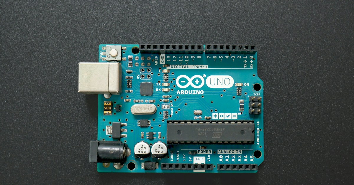
Arduino became popular in robotics because it made physical computing approachable: connect a board, read an input, and make something move. The platform’s official language reference provides the core functions, but a working robot requires more than memorizing digitalRead().
Early hobby robots often relied on:
- Bumper switches
- Infrared obstacle sensors
- Potentiometers for joint position
- Simple light-dependent resistors
- Ultrasonic modules such as the HC-SR04
Modern Arduino-based robots can combine:
- Inertial measurement units
- Time-of-flight distance sensors
- Wheel encoders
- Current sensors
- Color cameras
- Wireless sensor nodes
- ROS-compatible serial interfaces
That progression mirrors the wider shift from simple reactive machines to robots using sensor fusion, feedback control, and autonomous navigation. Our Robotics category explores those larger systems, while Arduino remains an excellent low-level controller for reading sensors and driving actuators.
From “if obstacle, turn” to closed-loop robotics
A basic robot might use logic like:
if (distanceCm < 20) {
 stopMotors();
 turnRight();
}
``

A more capable robot asks:

- Is the obstacle measurement reliable?
- Is the robot moving toward or away from it?
- Which sensor produced the reading?
- Is the wheel encoder reporting a stalled motor?
- Should the robot slow down rather than stop abruptly?
- Does the robot need to update a map?

That is the difference between **sensor input** and **robot perception**. The Arduino reads electrical signals; your software gives those signals meaning.

### Why Arduino remains useful

| Strength | Why it matters in robotics |
|---|---|
| Simple GPIO | Easy connection to switches, LEDs, drivers, and basic sensors |
| Mature ecosystem | Large library collection and extensive community support |
| Predictable embedded execution | Useful for timing, pulse measurement, and motor control |
| Low power consumption | Suitable for small mobile robots |
| Low-level access | You control pins, timers, interrupts, and communication buses |
| Educational value | Excellent for learning embedded programming and control systems |

### Where Arduino is not the whole solution

An Arduino Uno is not a replacement for a high-performance computer vision system or industrial safety controller. It has limited memory, processing power, and connectivity compared with a Raspberry Pi 5, NVIDIA Jetson, or industrial PLC.

Use Arduino for:

- Deterministic sensor sampling
- Motor-driver control
- Encoder counting
- Simple autonomous behaviors
- Hardware protyping
- Safety-adjacent monitoring, provided the actual safety function is independently engineered

Use a companion computer for:

- Computer vision
- Machine learning
- SLAM
- Large maps
- High-level path planning
- Complex [artificial intelligence](https://roboticcoding.com/category/artificial-intelligence/) workloads

## 🧰 What You Need Before Connecting Sensors to an Arduino

Before touching jumper wires, create a small interface plan. This takes minutes and can save an afternoon of mysterious readings.

### Choosing the Right Arduino Board for Your Robot

The board should match the sensor voltage, number of inputs, communication buses, timing requirements, and physical constraints.

| Arduino board | Logic voltage | Useful characteristics | Good robotics applications |
|---|---:|---|---|
| Arduino Uno R3 | 5 V | Familiar, robust ecosystem, easy protyping | Beginner robots, HC-SR04, switches, analog sensors |
| Arduino Nano | 5 V | Compact Uno-compatible layout | Small mobile robots and embedded prototypes |
| Arduino Mega 2560 | 5 V | Many GPIO pins and multiple hardware serial ports | Multi-sensor robots and robotic arms |
| Arduino Leonardo | 5 V | Native USB capability | USB-interactive projects and compact controllers |
| Arduino Nano 33 IoT | 3.3 V | Wi-Fi/Bluetooth connectivity and modern MCU | Connected robots and distributed sensors |
| Arduino Portenta H7 | 3.3 V | High-performance dual-core processing | Advanced embedded control and edge applications |

Check the board’s official electrical specifications at the [Arduino hardware portal](https://docs.arduino.cc/hardware/). **A 5 V sensor signal can damage a 3.3 V input**, even if the connector physically fits.

### Sensor Types: Analog, Digital, I2C, SPI, and UART

| Interface | Typical wires | Data style | Advantages | Common drawbacks |
|---|---|---|---|---|
| Analog | VCC, GND, signal | Voltage level | Simple and flexible | Noise, limited resolution, calibration required |
| Digital GPIO | VCC, GND, signal | HIGH/LOW | Easy and fast | Limited information |
| Pulse timing | VCC, GND, trigger, echo | Time duration | Useful for ultrasonic sensors and encoders | Timing-sensitive |
| I2C | VCC, GND, SDA, SCL | Addressed bus | Many devices on two signal wires | Address conflicts and pull-up requirements |
| SPI | VCC, GND, SCK, MOSI, MISO, CS | Synchronous serial | Fast and reliable | More wires and chip-select management |
| UART | VCC, GND, TX, RX | Serial stream | Simple point-to-point communication | Port availability and baud-rate matching |

A sensor’s connector does not tell you its protocol. The **datasheet does**. For example, a module may expose four pins but still use timing-based communication rather than ordinary digital input.

### Essential Wiring, Power, and Prototyping Tools

Keep these nearby:

- Breadboard or solderable protyping board
- Male-to-male and male-to-female jumper wires
- Digital multimeter
- USB cable appropriate for the Arduino board
- Regulated 5 V or 3.3 V supply
- Logic-level converter for incompatible voltage domains
- Resistors for pull-ups, pull-downs, and voltage dividers
- Decoupling capacitors
- Motor driver such as the [Polu DRV883](https://www.polu.com/product/2130)
- Screw terminals or locking connectors for mobile robots
- Heat-shrink tubing and cable ties
- A notebook or spreadsheet for pin assignments

For a first prototype, the [Arduino Uno R3](https://www.amazon.com/s?k=Arduino+Uno+R3&tag=bestbrands0a9-20&tag=bestbrands0a9-20) remains a sensible choice because documentation and compatible modules are plentiful.

👉 **CHECK PRICE on:**

- **Arduino Uno R3:** [Amazon](https://www.amazon.com/s?k=Arduino+Uno+R3&tag=bestbrands0a9-20&tag=bestbrands0a9-20) | [Arduino Official](https://store.arduino.cc/products/arduino-uno-rev3)
- **Arduino Mega 2560:** [Amazon](https://www.amazon.com/s?k=Arduino+Mega+2560&tag=bestbrands0a9-20) | [Arduino Official](https://store.arduino.cc/products/arduino-mega-2560-rev3)
- **Polu DRV883 Motor Driver:** [Amazon](https://www.amazon.com/s?k=Polu+DRV883&tag=bestbrands0a9-20) | [Polu Official](https://www.polu.com/product/2130)

## 🔌 How Arduino Sensor Wiring Works

Sensor wiring is not merely “connect the colors.” It is the construction of a small electrical communication system.

### Power, Ground, Signal, and Common Ground Rules

A basic sensor circuit has three relationships:

1. **Power** supplies energy.
2. **Ground** provides the reference voltage.
3. **Signal** communicates the measurement.

Suppose a sensor output is 3.0 V. The Arduino interprets that voltage relative to its ground. If the sensor and Arduino do not share a valid reference, the Arduino may see an unpredictable value.

#### Standard connection sequence

1. Turn off the Arduino and external supply.
2. Confirm the sensor’s operating voltage.
3. Connect sensor GND to Arduino GND.
4. Connect sensor VCC to the correct regulated rail.
5. Connect the signal wire to the documented Arduino pin.
6. Inspect for accidental shorts.
7. Power the sensor.
8. Measure VCC and GND with a multimeter.
9. Upload a minimal test sketch.
10. Only then connect motors or higher-power loads.

The [Arduino grounding and circuit documentation](https://docs.arduino.cc/) is a useful reference, but the sensor manufacturer’s pinout takes priority.

### Voltage Levels, Logic Compatibility, and Level Shifting

Common logic levels include:

- **5 V logic:** Arduino Uno, Mega, and many classic modules
- **3.3 V logic:** Arduino Nano 33 IoT, ESP32, many modern IMUs and sensors
- **24 V industrial I/O:** PLCs and many industrial robot controllers

A voltage divider may reduce a signal from 5 V to a safer 3.3 V level for a one-way input. A bidirectional logic-level converter is more appropriate for buses such as I2C.

Example voltage divider:

```text
5 V signal ─ R1 ─┬── Arduino 3.3 V input
 |
 R2
 |
 GND
``

The output is:

```text
Vout = Vin × R2 / (R1 + R2)
``

Do not use a divider blindly for fast signals, high-current loads, or bidirectional buses. The [Texas Instruments logic-level application resources](https://www.ti.com/product-category/logic-voltage-translation/voltage-translators-level-shifters/overview.html) explain why signal direction and speed matter.

### Pull-Up and Pull-Down Resistors for Reliable Readings

A floating input is electrically undecided. It may randomly alternate between HIGH and LOW when a switch is open.

Use:

```cpp
pinMode(buttonPin, INPUT_PULLUP);
``

Then wire the switch between the input pin and GND. The logic is inverted:

- Switch open: `HIGH`
- Switch closed: `LOW`

This internal pull-up approach is convenient for limit switches and bumper sensors. For I2C, external pull-up resistors are normally required, although many breakout boards include them. The [Arduino Wire library documentation](https://docs.arduino.cc/language-reference/functions/communication/wire/) explains the software side of I2C communication.

## 1. Connecting Analog Sensors to Arduino

Analog sensors produce a voltage within a defined range. Arduino’s analog-to-digital converter turns that voltage into a number.

On a classic Uno, `analogRead()` commonly returns a 10-bit value from **0 to 1023**, corresponding to the selected analog reference range. Confirm board-specific behavior in the [Arduino analog input reference](https://docs.arduino.cc/language-reference/functions/analog-io/analogRead/).

### Potentiometers, Force Sensors, and Flex Sensors

A potentiometer is an excellent teaching sensor because it exposes the essential voltage-divider concept.

#### Potentiometer wiring

- Outer terminal to 5 V
- Other outer terminal to GND
- Center wiper to `A0`

#### Test code

```cpp
const int sensorPin = A0;

void setup() {
 Serial.begin(115200);
}

void loop() {
 int rawValue = analogRead(sensorPin);

 Serial.print("Raw sensor value: ");
 Serial.println(rawValue);

 delay(50);
}
``

For a robotic arm, a potentiometer can represent joint position. For a gripper, a force-sensitive resistor can estimate contact pressure. Neither is automatically accurate: both need calibration and mechanical protection.

### Ultrasonic and Infrared Distance Sensors

Some distance sensors output analog voltage; others use digital timing or serial communication.

| Sensor | Interface | Strength | Limitation |
|---|---|---|---|
| Sharp GP2Y0A21YK | Analog | Simple obstacle-distance estimation | Nonlinear output and limited range |
| HC-SR04 | Trigger/echo timing | Inexpensive and easy to learn | Sensitive to angle, soft materials, and echoes |
| VL53L0X | I2C | Compact time-of-flight measurement | Requires library and correct voltage handling |
| VL53L1X | I2C | Longer-range time-of-flight capability | Optical conditions affect results |

The [STMicroelectronics VL53L1X documentation](https://www.st.com/en/imaging-and-photonics-solutions/vl53l1x.html) is the authoritative source for that sensor family.

### Reading Analog Voltage with `analogRead()`

A useful conversion begins with the reference voltage:

```cpp
const int sensorPin = A0;
const float referenceVoltage = 5.0;

void setup() {
 Serial.begin(115200);
}

void loop() {
 int raw = analogRead(sensorPin);
 float voltage = raw * referenceVoltage / 1023.0;

 Serial.print("Raw: ");
 Serial.print(raw);
 Serial.print(" | Voltage: ");
 Serial.println(voltage, 3);

 delay(100);
}
``

For a 3.3 V board, change the reference value only if it accurately represents the ADC reference. Better still, use the board documentation and measure the actual rail.

### Calibrating Analog Sensors for Robotic Movement

Calibration should record:

- Minimum expected reading
- Maximum expected reading
- Mechanical zero
- Sensor response curve
- Temperature effects
- Repeatability
- Saturation points

For a joint sensor:

```cpp
int jointAngle = map(raw, rawMin, rawMax, 0, 180);
jointAngle = constrain(jointAngle, 0, 180);
``

`map()` performs linear scaling, but many sensors are nonlinear. A lookup table or fitted curve may produce better robotic motion.

## 2. Connecting Digital Sensors and Switches

Digital sensors communicate with discrete states, pulses, or transitions. They are often the most reliable starting point for a robot because the software model is straightforward.

### Limit Switches, Encoders, and Hall-Effect Sensors

#### Limit switch wiring

```text
Arduino pin ─ switch ─ GND
``

Code:

```cpp
const byte limitPin = 7;

void setup() {
 pinMode(limitPin, INPUT_PULLUP);
 Serial.begin(115200);
}

void loop() {
 bool activated = digitalRead(limitPin) == LOW;

 if (activated) {
 Serial.println("Limit reached");
 }

 delay(10);
}
``

A limit switch can prevent a robotic arm from driving beyond a mechanical boundary, but **software alone should not be treated as a complete safety system**.

Hall-effect sensors detect magnetic fields and work well for wheel speed or end-stop detection. Encoders provide more detailed position feedback. The [Arduino attachInterrupt() reference](https://docs.arduino.cc/language-reference/functions/external-interupts/attachInterrupt/) explains how to respond to fast transitions.

### PIR Motion and Obstacle Detection Sensors

A PIR sensor typically provides a HIGH output when it detects a change infrared radiation. It is useful for human-presence experiments but is not a precision obstacle sensor for a fast mobile robot.

For robot navigation, consider:

- Time-of-flight sensors
- Ultrasonic sensors
- Infrared proximity modules
- Wheel encoders
- 2D lidar
- Depth cameras

The right sensor depends on speed, range, lighting, surface material, and required response time.

### Using `digitalRead()`, Interrupts, and Debouncing

A mechanical switch can bounce electrically for several milliseconds. Without debouncing, one press may look like many presses.

#### Software debounce with `millis()`

```cpp
const byte buttonPin = 2;
bool stableState = HIGH;
bool lastReading = HIGH;
unsigned long lastChange = 0;
const unsigned long debounceMs = 30;

void setup() {
 pinMode(buttonPin, INPUT_PULLUP);
 Serial.begin(115200);
}

void loop() {
 bool reading = digitalRead(buttonPin);

 if (reading != lastReading) {
 lastChange = millis();
 }

 if (millis() - lastChange > debounceMs) {
 if (reading != stableState) {
 stableState = reading;

 if (stableState == LOW) {
 Serial.println("Button event");
 }
 }
 }

 lastReading = reading;
}
``

For high-speed encoders, interrupts may be necessary. For slow buttons, polling with debouncing is simpler and easier to debug.

## 3. Connecting I2C Sensors to Arduino

I2C is popular in robotics because multiple sensors can share two signal wires.

### SDA and SCL Wiring on Popular Arduino Boards

| Board | SDA | SCL |
|---|---|---|
| Arduino Uno R3 | A4 | A5 |
| Arduino Nano | A4 | A5 |
| Arduino Mega 2560 | 20 | 21 |
| Arduino Leonardo | 2 | 3 |
| Many modern boards | Board-specific | Board-specific |

Always verify the board pinout at [Arduino’s official pinout documentation](https://docs.arduino.cc/hardware/).

Typical I2C wiring:

- Sensor VCC to the correct supply
- Sensor GND to Arduino GND
- Sensor SDA to Arduino SDA
- Sensor SCL to Arduino SCL

### Installing Libraries and Scanning I2C Addresses

Libraries reduce the amount of register-level code you must write. Use the Arduino IDE Library Manager or the manufacturer’s official repository.

An I2C scanner can reveal whether a device responds:

```cpp
# include <Wire.h>

void setup() {
 Wire.begin();
 Serial.begin(115200);
 while (!Serial) {}

 Serial.println("I2C scanner");
}

void loop() {
 byte error;
 int found = 0;

 for (byte address = 1; address < 127; address++) {
 Wire.beginTransmission(address);
 error = Wire.endTransmission();

 if (error == 0) {
 Serial.print("Found device at 0x");
 if (address < 16) Serial.print("0");
 Serial.println(address, HEX);
 found++;
 }
 }

 if (found == 0) {
 Serial.println("No I2C devices found");
 }

 delay(300);
}
``

If the scanner finds nothing, check:

- Power voltage
- Ground
- SDA/SCL reversal
- Pull-up resistors
- Board pin mapping
- Sensor address-selection pins
- Whether the module is actually I2C rather than SPI

### Using MPU6050, BNO055, and Time-of-Flight Sensors

The **MPU6050** combines an accelerometer and gyroscope. The **BNO055** adds onboard sensor fusion, which can simplify orientation estimates. The **VL53L0X** and **VL53L1X** use time-of-flight measurement for distance sensing.

| Sensor | Main data | Typical robotic use |
|---|---|---|
| MPU6050 | Acceleration and angular velocity | Balance, motion detection, orientation estimation |
| BNO055 | Fused orientation | Robot heading and arm orientation |
| VL53L0X | Distance | Short-range obstacle detection |
| VL53L1X | Distance and ranging modes | Navigation and presence detection |

The [Adafruit BNO055 guide](https://learn.adafruit.com/adafruit-bno055-absolute-orientation-sensor) and [Adafruit VL53L0X guide](https://learn.adafruit.com/adafruit-vl53l0x-micro-lidar-distance-sensor-breakout) provide practical wiring and library examples.

### Resolving I2C Address Conflicts

Two identical sensors may share the same default address. Solutions include:

- Change the address if the sensor supports it.
- Use an enable or shutdown pin to initialize devices one at a time.
- Add an I2C multiplexer such as the **TCA9548A**.
- Use separate hardware buses where the board supports them.

The [Adafruit TCA9548A breakout](https://www.adafruit.com/product/2717) is a common solution for multiple identical I2C modules.

## 4. Connecting SPI and UART Sensors

### SPI Wiring: MOSI, MISO, SCK, and Chip Select

SPI generally uses:

- **SCK**: clock
- **MOSI**: controller to peripheral
- **MISO**: peripheral to controller
- **CS/SS**: selects one peripheral
- VCC and GND

Each SPI device usually needs its own chip-select line. SPI is faster than I2C in many applications, making it useful for displays, fast ADCs, memory, and certain sensors.

The [Arduino SPI reference](https://docs.arduino.cc/language-reference/functions/communication/spi/) documents the standard library.

### UART Sensors, Serial Ports, and GPS Modules

UART wiring is crossed:

- Sensor TX → Arduino RX
- Sensor RX → Arduino TX
- Sensor GND → Arduino GND

Both devices must use compatible:

- Baud rate
- Data bits
- Parity
- Stop bits
- Logic voltage

The Arduino Mega is particularly useful when a robot needs one serial port for debugging and another for a sensor or motor controller.

### Avoiding Serial Monitor and Sensor Communication Conflicts

On an Uno, pins 0 and 1 are connected to the USB serial interface. Connecting a UART sensor there can interfere with uploading and debugging.

Options include:

- Use `SoftwareSerial` for slower devices.
- Use an Arduino Mega with multiple hardware serial ports.
- Use a board with additional UARTs.
- Temporarily disconnect the sensor during upload.

For timing-sensitive robotics, hardware serial is usually preferable.

## 5. Connecting Motion, Position, and Orientation Sensors

Motion feedback turns a robot from an open-loop machine into a system that can detect what actually happened.

### Rotary Encoders for Wheel and Joint Feedback

A quadrature encoder provides two phase-shifted signals. By comparing their order, the Arduino can determine direction as well as movement.

Encoder data helps estimate:

- Wheel rotation
- Linear travel
- Joint angle
- Motor stall conditions
- Odometry

A basic encoder count is not the same as accurate position. Wheel slip, gearbox backlash, and uneven surfaces create error. That is why autonomous robots often combine encoders with inertial and distance sensors.

### Accelerometers, Gyroscopes, and IMUs

An IMU can detect:

- Tilt
- Rotation rate
- Suden impacts
- Vibration
- Changes in motion

Raw accelerometer data is noisy and affected by gravity. Gyroscope data drifts over time. Sensor fusion combines both strengths.

For advanced filtering and estimation, our [Robotic Simulations category](https://roboticcoding.com/category/robotic-simulations/) offers useful context on testing control behavior before risking hardware.

### Servo Position Feedback and Robotic Arm Sensing

A standard hobby servo usually receives a control pulse but does not expose its internal position to Arduino. If you need actual joint feedback, use:

- A servo with feedback output
- An external potentiometer
- An absolute magnetic encoder
- An incremental encoder
- A current sensor for indirect load detection

**Commanded position is not measured position.** That distinction matters when a gripper hits an object or a joint encounters resistance.

## 6. Connecting Environmental and Safety Sensors

### Temperature, Humidity, Pressure, and Gas Sensors

Environmental sensors can support:

- Battery thermal monitoring
- Indoor mapping
- Weather robots
- Equipment protection
- Gas-leak experiments
- Altitude estimation

Examples include:

- **BME280** for temperature, humidity, and pressure
- **DHT22** for basic temperature and humidity
- **SCD40** for carbon-dioxide measurement
- **MQ-series modules** for experimental gas detection

Gas sensors often require warm-up time and calibration. Do not treat a hobby gas module as a certified life-safety instrument.

### Light, Color, and Line-Following Sensors

Line-following robots commonly use infrared reflectance sensors. A black line absorbs more infrared energy than a light surface, producing a measurable contrast.

Color sensors such as the **TCS34725** can estimate red, green, blue, and clear-channel intensity. Ambient light, distance, and surface finish affect readings.

### Bumper, Current, and Battery-Voltage Monitoring

A robust robot monitors itself as well as its surroundings.

Useful sensors include:

- Bumper switches for contact detection
- INA219 or INA226 for current and voltage monitoring
- Voltage dividers for battery measurement
- Thermistors for motor or battery temperature
- Hall sensors for rotational feedback

The [Texas Instruments INA219 documentation](https://www.ti.com/product/INA219) explains the shunt-monitoring principle. Add appropriate fuses, protection, and filtering when working with batteries.

## 🧠 Arduino Sensor Code for Robotics

### A Reliable Sensor-Reading Program Structure

Separate the program into layers:

1. **Acquisition**: read raw sensor data.
2. **Validation**: reject impossible or stale values.
3. **Filtering**: reduce noise.
4. **Interpretation**: convert readings into meaningful units.
5. **Decision-making**: choose a behavior.
6. **Actuation**: command motors or servos.
7. **Diagnostics**: report state and faults.

A compact structure might look like this:

```cpp
struct SensorData {
 float distanceCm;
 bool bumperPressed;
 int batteryMillivolts;
};

SensorData readSensors() {
 SensorData data;

 data.distanceCm = readDistanceCm();
 data.bumperPressed = digitalRead(7) == LOW;
 data.batteryMillivolts = readBatteryMillivolts();

 return data;
}

void loop() {
 SensorData sensors = readSensors();

 if (sensors.bumperPressed || sensors.distanceCm < 15.0) {
 stopMotors();
 } else {
 driveForward();
 }
``

This structure makes testing easier than scattering sensor reads throughout motor-control code.

### Filtering Noise with Averaging and Moving Filters

A moving average reduces random variation:

```cpp
const byte sampleCount = 8;
int samples[sampleCount];
byte index = 0;

int readSmoothedAnalog(byte pin) {
 samples[index] = analogRead(pin);
 index = (index + 1) % sampleCount;

 long total = 0;
 for (byte i = 0; i < sampleCount; i++) {
 total += samples[i];
 }

 return total / sampleCount;
}
``

Filtering introduces delay. A robot moving quickly may need a faster filter or a median filter that rejects occasional spikes.

### Sensor Fusion for Better Robot Decisions

Imagine an obstacle sensor reports 12 cm, but the wheel encoder says the robot has not moved and the IMU detects vibration. That reading may be real, noisy, or caused by a nearby angled surface.

Sensor fusion can combine:

- Ultrasonic distance
- Infrared distance
- Wheel odometry
- IMU orientation
- Bumper state

A simple confidence strategy:

```cpp
bool obstacleDetected(float ultrasonicCm, int irValue, bool bumper) {
 bool ultrasonicClose = ultrasonicCm > 0 && ultrasonicCm < 20;
 bool infraredClose = irValue > 700;

 return bumper || (ultrasonicClose && infraredClose);
}
``

This reduces false positives but may miss obstacles detected by only one sensor. The correct rule depends on the robot’s environment.

### Mapping Sensor Values to Motors and Actuators

Raw sensor values should not directly produce uncontrolled motor commands.

Use:

- Saturation limits
- Dead zones
- Acceleration ramps
- Fault states
- Watchdogs
- Direction interlocks

For example:

```cpp
int speedFromDistance(float distanceCm) {
 if (distanceCm <= 10) return 0;
 if (distanceCm >= 80) return 200;

 return map((int)distanceCm, 10, 80, 0, 200);
}
``

### Using `millis()` Instead of Blocking `delay()`

A robot that spends too long inside `delay()` may miss encoder pulses or fail to react to a bumper.

```cpp
unsigned long lastSensorRead = 0;
const unsigned long sensorPeriod = 20;

void loop() {
 unsigned long now = millis();

 if (now - lastSensorRead >= sensorPeriod) {
 lastSensorRead = now;
 updateSensors();
 }

 updateMotors();
 updateSafety();
 updateCommunications();
}
``

This cooperative scheduling style is often enough for small robots. More complex systems may need a real-time operating system or a companion controller.

## ⚙️ Connecting Sensors to Motors, Servos, and Robot Controllers

### Separating Sensor Power from Motor Power

Motors create electrical noise and sudden current demand. If a motor and sensor share a weak supply rail, the sensor may reset or produce corrupted readings.

Recommended arrangement:

- Battery → motor driver power
- Battery → regulated sensor supply
- Arduino → logic and control signals
- Common reference ground where the interface requires it
- Decoupling capacitors near sensors and drivers

Do not power large motors directly from an Arduino 5 V pin. The [Arduino Uno technical specifications](https://docs.arduino.cc/hardware/uno-rev3) show the board’s electrical limits.

### Motor Drivers, PWM, and Control Signals

An Arduino pin controls a motor driver; it does not normally drive a motor directly.

Common drivers include:

- Polu DRV883
- TB6612FNG breakout boards
- Adafruit Motor Shield
- Cytron motor controllers

A driver handles current switching while Arduino supplies direction and PWM commands.

### Closed-Loop Control with Sensor Feedback

Open-loop command:

```text
Set motor power to 150 and hope the robot moves as expected.
``

Closed-loop command:

```text
Measure position → compare with target → adjust motor command.
``

Feedback can come from:

- Encoders
- Potentiometers
- IMUs
- Current sensors
- Limit switches
- External vision systems

### PID Control for Robotic Motion

A PID controller uses:

- **Proportional** error for immediate correction
- **Integral** error for accumulated offset
- **Derivative** error for rate of change

```text
output = Kp × error + Ki × accumulatedError + Kd × errorRate
``

Poorly tuned PID can cause oscillation, sluggish response, or integral windup. Begin with proportional control, add derivative damping, then introduce a small integral term only when necessary.

## 🛠️ Building a Multi-Sensor Arduino Robot

### Planning Pins, Buses, and Sensor Addresses

Create a pin map before wiring:

| Function | Device | Interface | Arduino connection |
|---|---|---|---|
| Front distance | HC-SR04 | Trigger/echo | D9/D10 |
| Left distance | VL53L0X | I2C | SDA/SCL |
| Wheel encoder | Hall sensor | Interrupt input | D2 |
| Bumper | Limit switch | Digital input | D7 |
| Battery monitor | Voltage divider | Analog | A0 |
| Motor driver | DRV883 | PWM/GPIO | D5/D6/D8 |

Reserve pins for:

- Debuging
- Emergency stop input
- Future sensors
- Status LEDs
- Communication

### Wiring an Obstacle-Avoiding Mobile Robot

A practical sequence:

1. Connect Arduino and one distance sensor.
2. Confirm stable readings with motors disconnected.
3. Add the motor driver and test one motor at low duty cycle.
4. Add the second motor.
5. Connect wheel feedback.
6. Add battery monitoring.
7. Test on blocks so wheels can spin safely.
8. Test at low speed on the floor.
9. Add filtering and obstacle behavior.
10. Test failure cases: unpluged sensor, blocked wheel, low battery.

The first video linked at [#featured-video](#featured-video) demonstrates the classic HC-SR04 setup: **VCC to 5 V, GND to GND, trigger to digital pin 9, and echo to digital pin 10**. Its explanation correctly emphasizes starting with a clean signal, using `delayMicroseconds()`, and dividing the round-trip echo time by two. That is a useful beginner demonstration, but a mobile robot needs additional filtering, timeout handling, and motor-noise testing.

### Wiring an Arduino Robotic Arm with Joint Sensors

For each joint:

- Motor or servo driver
- Position sensor
- Mechanical limit
- Optional current measurement
- Software travel limits

A safe joint routine should:

1. Read the joint sensor.
2. Validate the value.
3. Check the limit switch.
4. Compare measured position with target.
5. Apply a bounded motor command.
6. Stop on sensor failure or unexpected motion.

### Expanding Inputs with Multiplexers and Port Expanders

When pins run out, consider:

- CD74HC4067 analog multiplexer
- MCP23017 I2C GPIO expander
- PCF8574 I2C expander
- ADS1115 external ADC
- Arduino Mega
- A second microcontroller

Expansion adds complexity. A multiplexer can share one ADC, but it introduces switching time and settling requirements. An external ADC may improve resolution, but only if the sensor and wiring justify it.

## 🔋 Power Management and Electrical Protection

### Calculating Sensor Current and Battery Requirements

List every load:

| Load | Voltage | Current estimate | Notes |
|---|---:|---:|---|
| Arduino board | Board-specific | Datasheet value | Add USB or regulator losses |
| Distance sensor | 3.3 V or 5 V | Datasheet value | Check peak current |
| IMU | 3.3 V | Datasheet value | Sensitive to supply noise |
| Motor driver logic | 3.3 V or 5 V | Datasheet value | Separate motor current |
| Motors | Battery voltage | High and variable | Stall current matters |

Design for startup and stall conditions, not only average current. A motor can draw far more current when blocked than while spinning freely.

### Regulators, Decoupling Capacitors, and Brownout Prevention

Use:

- A regulator sized for peak sensor current
- Ceramic capacitors close to sensor VCC/GND
- Bulk electrolytic capacitors near motor drivers
- Short, sensible power paths
- Separate wiring for high-current motor loops

A brownout may look like a software bug because the Arduino resets, loses serial output, or returns to its startup routine.

### Protecting Arduino Inputs from Overvoltage and Reverse Polarity

Protection options include:

- Resistor dividers
- Series resistors
- TVS diodes
- Schottky clamps
- Fuses
- Reverse-polarity protection
- Optocouplers
- Isolated DC-DC converters

Choose protection based on the fault you expect. A resistor divider does not protect against every transient, and an optocoupler does not automatically solve incorrect grounding.

### Managing Electrical Noise from Motors and Servos

Try:

- Twisted motor wires
- Physical separation between motor and sensor cables
- Ferrite beads where appropriate
- Capacitors across brushed motor terminals
- Star-style power distribution
- Shielded or twisted signal wiring
- Software filtering
- Lower PWM edge noise where practical

If readings fail only when motors run, suspect **power integrity and electromagnetic interference before rewriting the entire sketch**.

## 🧪 Testing, Calibration, and Debuging Sensor Connections

### A Safe Step-by-Step Wiring Test

1. Read the datasheet.
2. Identify voltage and pin functions.
3. Check continuity with power disconnected.
4. Power only the sensor and Arduino.
5. Measure VCC at the sensor pins.
6. Run an I2C scanner or minimal GPIO sketch.
7. Print raw values over Serial.
8. Move or stimulate the sensor manually.
9. Record minimum, maximum, and abnormal readings.
10. Connect the actuator system last.

### Using a Multimeter, Logic Analyzer, and Serial Monitor

A multimeter verifies:

- Supply voltage
- Ground continuity
- Battery voltage
- Analog output range

A logic analyzer reveals:

- I2C address activity
- SPI clock and data
- UART baud mismatch
- Missing trigger pulses
- Encoder transitions

The Serial Monitor helps, but it cannot show every timing or electrical problem. Tools such as the [Saleae Logic analyzer](https://www.saleae.com/) can make invisible communication faults visible.

### Diagnosing Noisy, Frozen, or Impossible Sensor Values

| Symptom | Likely causes | First checks |
|---|---|---|
| Always zero | No power, wrong pin, missing ground | Measure VCC and inspect pinout |
| Always maximum | Floating input, saturated sensor, wrong reference | Add pull-up/down and verify range |
| Random values | Noise, loose wire, floating input | Secure wiring and add filtering |
| I2C device missing | Wrong pins, address conflict, voltage issue | Run scanner and inspect pull-ups |
| Works until motors start | Brownout or EMI | Separate supplies and add decoupling |
| Arduino resets | Current surge or short | Check regulator and motor stall current |
| Distance jumps | Echo interference or poor geometry | Add timeout, filtering, and sensor spacing |
| Encoder misses counts | Polling too slowly or noisy edges | Use interrupts and improve wiring |

### Common Arduino Sensor Wiring Mistakes

❌ Connecting a 5 V output to a 3.3 V-only input
❌ Forgeting the common ground
❌ Powering motors from the Arduino regulator
❌ Reversing SDA and SCL
❌ Using the wrong board pin numbers
❌ Leaving digital inputs floating
❌ Assuming a relay module’s coil voltage matches its contact rating
❌ Ignoring sensor warm-up and calibration
❌ Using `delay()` in a high-speed encoder loop
❌ Treating a hobby sensor as a certified safety device

## 📡 Wireless and Networked Sensor Options

### Bluetooth, Wi-Fi, and ESP32 Sensor Nodes

Wireless sensor nodes can reduce cable clutter, but they add:

- Latency
- Packet loss
- Pairing and connection management
- Power consumption
- Security concerns
- More complicated fault handling

An **ESP32** is often a better wireless sensor node than a classic Uno because it includes Wi-Fi and Bluetooth. See the [Espressif ESP32 documentation](https://docs.espressif.com/projects/esp-idf/en/latest/esp32/) for platform details.

### Sending Arduino Sensor Data to ROS and a Raspberry Pi

A common architecture is:

```text
Sensors → Arduino → Serial/USB → Raspberry Pi or PC → ROS/navigation stack
``

Arduino handles:

- Fast GPIO
- Encoder counting
- Motor-driver commands
- Deterministic low-level loops

The companion computer handles:

- Mapping
- Planning
- Vision
- Logging
- User interfaces

This division is useful when a robot needs both reliable hardware timing and sophisticated software. Our [Robotic Simulations](https://roboticcoding.com/category/robotic-simulations/) and [Coding Languages](https://roboticcoding.com/category/coding-languages/) categories provide related programming context.

### When to Use Wired Versus Wireless Sensors

| Requirement | Better choice |
|---|---|
| Safety-related stop signal | Wired, independently engineered |
| Wheel encoder | Wired |
| Removable environmental probe | Wireless may be suitable |
| High-rate IMU | Wired |
| Distributed warehouse sensor | Wireless with monitoring |
| Prototype telemetry | Bluetooth or Wi-Fi |
| Industrial robot I/O | Certified wired interface |

## 🦾 Arduino Sensor Integration for Industrial and Collaborative Robots

### Analog Wiring to a UR5 and Other Robot Controllers

This is where hobby wiring meets industrial voltage, and the rules change.

The Universal Robots forum discussion on configurable inputs states that **UR5e inputs and outputs operate at 24 V**, while Arduino outputs are commonly 3.3 V or 5 V. The practical recommendation is not to connect those signals directly. As the discussion puts it, **“A relay allows you to switch a higher voltage using a lower voltage control.”** Read the original discussion at [Connecting Arduino to configurable inputs](https://forum.universal-robots.com/t/connecting-arduino-to-configurable-inputs/27859).

A relay interface typically works like this:

1. Arduino reads a sensor.
2. Arduino drives a relay module input.
3. The relay coil energizes.
4. The relay’s isolated contact switches the robot-side circuit.
5. The UR5 input detects the appropriate 24 V state.

The forum example describes connecting the robot’s 24 V supply to relay **COM**, then connecting the robot input to **NO**. That arrangement leaves the input inactive until the Arduino commands it.

**Do not copy a relay module solely because its contacts are rated “30 V, 10 A.”** You must also verify:

- Coil voltage
- Coil current
- Contact configuration
- Contact rating for the actual load
- Isolation
- Suppression requirements
- Robot-controller wiring rules
- Safety category and risk assessment

For industrial integration, a properly selected optocoupler, interposing relay, or certified interface module may be more appropriate than a hobby relay board.

### Signal Isolation, Safety Circuits, and Emergency Stops

An Arduino should not be the sole component responsible for an emergency stop. Emergency-stop functions must be designed according to applicable machinery-safety requirements and the robot manufacturer’s instructions.

Use the [Universal Robots support and documentation resources](https://www.universal-robots.com/articles/) for controller-specific information. The separate forum page about [Arduino analog wiring to a UR5](https://forum.universal-robots.com/t/arduino-analog-wiring-to-ur5/27085) is relevant as a discussion link, but the supplied page content does not establish a complete wiring procedure or validated electrical specification.

### Arduino Limitations in Production Robotics

Arduino is excellent for prototypes, fixtures, educational robots, and low-level experiments. Production systems may require:

- Certified safety I/O
- Deterministic industrial networks
- EMC compliance
- Traceable components
- Watchdog architecture
- Fault logging
- Redundant sensing
- Validated software
- Environmental protection

The right question is not “Can Arduino read this sensor?” It is **“Can the complete system meet the required reliability, safety, and compliance target?”**

## ✅ Sensor Connection Best Practices and Quick Reference

### Do’s and Don’ts for Reliable Robotic Sensor Wiring

| ✅ Do | ❌ Don’t |
|---|---|
| Read the datasheet | Guess from wire colors |
| Confirm voltage levels | Connect incompatible logic directly |
| Share a valid ground reference | Leave inputs floating |
| Test sensors before motors | Debug everything at once |
| Use filtering thoughtfully | Hide bad wiring with excessive averaging |
| Separate motor and sensor power | Power motors from Arduino pins |
| Label every wire | Trust memory after a late-night rebuild |
| Add timeouts and fault states | Assume a sensor always responds |
| Use hardware interrupts for fast encoders | Poll high-speed signals too slowly |
| Document pin assignments | Reuse pins accidentally |

### Arduino Sensor Interface Comparison Table

| Sensor need | Recommended interface | Example device | Best use |
|---|---|---|---|
| Simple switch | Digital GPIO with pull-up | Omron limit switch | End stops and bumpers |
| Variable position | Analog input | Potentiometer | Joint feedback |
| Short-range distance | I2C time-of-flight | VL53L0X | Compact obstacle sensing |
| Beginner distance project | Trigger/echo | HC-SR04 | Learning and slow robots |
| Orientation | I2C | BNO055 | Arm and mobile robot attitude |
| Wheel movement | Interrupt GPIO | Hall encoder | Odometry |
| High-speed sensor stream | SPI | External ADC or IMU | Fast sampling |
| Industrial controller interface | Isolated relay or interface | Phoenix Contact module | 24 V I/O integration |

### Practical Sensor Selection Checklist

Before buying or wiring a sensor, ask:

- What is the measurement range?
- What accuracy does the robot actually need?
- What is the update rate?
- What voltage does it require?
- Is the output analog, digital, I2C, SPI, or UART?
- Does it need pull-up resistors?
- Does it have a stable library?
- Can it tolerate vibration and dust?
- Does its field of view suit the robot?
- What happens when the sensor disconnects?
- Can the Arduino process the data quickly enough?
- Is the sensor appropriate for a safety function?

## ❌ Safety Warnings for Arduino Robotics Projects

- Disconnect power before changing wiring.
- Never short a battery or regulated supply.
- Keep fingers, hair, and loose clothing away from moving mechanisms.
- Test mobile robots with wheels lifted first.
- Add a physical power disconnect.
- Use fuses appropriate to the battery and wiring.
- Do not connect Arduino pins directly to industrial 24 V I/O.
- Do not assume a relay module provides certified safety isolation.
- Treat lithium battery packs with appropriate charging and protection equipment.
- Use independent safety circuits for hazardous machinery.
- Add watchdogs and fail-safe states where a software fault could cause motion.
- Verify every external module’s voltage before plugging it into an Arduino.

## Conclusion

Connecting sensors to an Arduino for robotic applications follows a repeatable pattern: **identify the interface, match the voltage, wire power and ground correctly, read raw data, validate it, filter it, and only then use it to control motion**.

Our strongest recommendations are:

- Start with an **Arduino Uno R3** and a single sensor for learning.
- Use the **HC-SR04** to understand trigger-and-echo timing.
- Move to **VL53L0X/VL53L1X** time-of-flight sensors when compact I2C distance sensing is more useful.
- Choose **BNO055 or MPU6050** modules for orientation experiments.
- Add wheel encoders before attempting serious autonomous navigation.
- Separate motor power from sensor power.
- Use interrupts for fast encoder signals.
- Use level shifting or isolation whenever voltage domains differ.
- Treat UR5 and other industrial robot interfaces as **24 V control systems**, not oversized Arduino pins.
- Keep emergency-stop and safety functions independent from hobby-level firmware.

The unresolved question from the beginning now has a clear answer: a sensor does not make a robot intelligent merely by being connected. Reliable robotics comes from the complete chain: **electrical integrity → accurate measurement → robust code → feedback control → safe actuation**.

## Recommended Links

👉 **CHECK PRICE on:**

- **Arduino Uno R3:** [Amazon](https://www.amazon.com/s?k=Arduino+Uno+R3&tag=bestbrands0a9-20&tag=bestbrands0a9-20) | [Arduino Official](https://store.arduino.cc/products/arduino-uno-rev3)
- **Arduino Mega 2560:** [Amazon](https://www.amazon.com/s?k=Arduino+Mega+2560&tag=bestbrands0a9-20) | [Arduino Official](https://store.arduino.cc/products/arduino-mega-2560-rev3)
- **Arduino Nano 33 IoT:** [Amazon](https://www.amazon.com/s?k=Arduino+Nano+33+IoT&tag=bestbrands0a9-20) | [Arduino Official](https://store.arduino.cc/products/arduino-nano-33-iot)
- **HC-SR04 Ultrasonic Sensor:** [Amazon](https://www.amazon.com/s?k=HC-SR04+ultrasonic+sensor&tag=bestbrands0a9-20) | [Arduino Ultrasonic Guide](https://docs.arduino.cc/libraries/hc-sr04/)
- **VL53L0X Time-of-Flight Sensor:** [Amazon](https://www.amazon.com/s?k=VL53L0X+time+of+flight+sensor&tag=bestbrands0a9-20) | [STMicroelectronics Official](https://www.st.com/en/imaging-and-photonics-solutions/vl53l0x.html)
- **BNO055 Orientation Sensor:** [Amazon](https://www.amazon.com/s?k=BNO055+orientation+sensor&tag=bestbrands0a9-20) | [Adafruit Official](https://learn.adafruit.com/adafruit-bno055-absolute-orientation-sensor)
- **MPU6050 IMU:** [Amazon](https://www.amazon.com/s?k=MPU6050+IMU+Arduino&tag=bestbrands0a9-20) | [TDK InvenSense Official](https://invense.tdk.com/products/motion-tracking/6-axis/mpu-6050/)
- **TCA9548A I2C Multiplexer:** [Amazon](https://www.amazon.com/s?k=TCA9548A+I2C+multiplexer&tag=bestbrands0a9-20) | [Adafruit Official](https://www.adafruit.com/product/2717)
- **Polu DRV883 Motor Driver:** [Amazon](https://www.amazon.com/s?k=Polu+DRV883&tag=bestbrands0a9-20+motor+driver) | [Polu Official](https://www.polu.com/product/2130)
- **INA219 Current Sensor:** [Amazon](https://www.amazon.com/s?k=INA219+current+sensor&tag=bestbrands0a9-20) | [Texas Instruments Official](https://www.ti.com/product/INA219)
- **Arduino Robotics Books:** [Amazon](https://www.amazon.com/s?k=Arduino+robotics+book&tag=bestbrands0a9-20)

## FAQ

### What sensors are commonly used in Arduino robotics projects?

Common choices include:

- **HC-SR04** ultrasonic sensors for basic distance measurement
- **VL53L0X and VL53L1X** time-of-flight sensors for compact ranging
- **IR reflectance sensors** for line following
- **MPU6050 and BNO055** IMUs for motion and orientation
- **Rotary encoders** for wheel and joint feedback
- **Limit switches** for mechanical boundaries
- **INA219** modules for current and voltage monitoring
- **BME280** modules for environmental sensing

The best sensor depends on range, update rate, lighting, surface material, voltage, and required accuracy. A cheap ultrasonic sensor may be perfect for a slow classroom robot but unsuitable for a fast robot navigating crowded spaces.

### How do you wire multiple sensors to an Arduino for a robot?

Use a pin and bus plan before wiring.

- Analog sensors use separate analog inputs.
- Digital switches use separate GPIO pins.
- I2C sensors share SDA and SCL but require unique addresses.
- SPI sensors share clock and data lines but usually need separate chip-select pins.
- UART sensors need compatible serial ports and crossed TX/RX wiring.

If two I2C sensors have the same address, change their addresses, use shutdown sequencing, or add a TCA9548A multiplexer.

### How do you program Arduino sensors for robotic applications?

Use a layered program:

1. Initialize pins and libraries.
2. Read raw values.
3. Check for invalid or missing data.
4. Convert readings into useful units.
5. Filter noise.
6. Apply thresholds or control algorithms.
7. Command actuators.
8. Log faults and sensor status.

Avoid placing long `delay()` calls in code that must monitor encoders, bumpers, or safety inputs. Use `millis()` scheduling or interrupts where appropriate.

### How do you connect ultrasonic and infrared sensors to an Arduino robot?

For a typical HC-SR04:

- VCC → Arduino 5 V
- GND → Arduino GND
- TRIG → digital output
- ECHO → digital input

The Arduino sends a short trigger pulse, measures the echo duration, and converts the round-trip time into distance. Add a timeout so a missing echo does not block the program.

Infrared sensors vary widely. A reflectance module may provide a digital threshold output, while a Sharp distance sensor may provide analog voltage. Follow the exact module pinout and voltage requirements.

### What Arduino libraries are needed to use sensors in robotics?

The library depends on the sensor:

- `Wire.h` for I2C
- `SPI.h` for SPI
- `Servo.h` for hobby servos
- `SoftwareSerial.h` for software UART on supported boards
- `Adafruit_BNO055.h` for BNO055 modules
- `Adafruit_VL53L0X.h` for compatible VL53L0X boards
- `Adafruit_INA219.h` for INA219 modules

Prefer manufacturer-maintained or widely supported libraries, and verify board compatibility before building the complete robot.

### How do you troubleshoot sensor connections on an Arduino robot?

Start with the simplest possible test:

1. Disconnect motors.
2. Confirm sensor VCC and GND with a multimeter.
3. Verify the pinout.
4. Run an I2C scanner if applicable.
5. Print raw readings.
6. Move or stimulate the sensor manually.
7. Check for floating inputs.
8. Add filtering only after wiring is sound.
9. Reconnect motors and observe whether failures begin under load.
10. Inspect for brownouts, EMI, and loose connectors.

A sensor that fails only when motors run usually points to power integrity or electrical noise rather than a library problem.

### How can sensor data improve autonomous robot navigation?

Sensor data supports:

- Obstacle detection
- Wall following
- Line following
- Odometry
- Localization
- Collision prevention
- Speed adaptation
- Battery-aware behavior

Combining sensors is usually stronger than relying one. Encoders estimate movement, IMUs estimate rotation, and distance sensors detect the environment. Together, they can reduce uncertainty and improve navigation decisions.

### Can an Arduino connect directly to a UR5 or other 24 V robot controller?

Usually, **not directly**. Arduino Uno and similar boards commonly output 5 V or 3.3 V logic, while industrial robot I/O may use 24 V. Use an appropriately rated isolated interface, relay, optocoupler, or industrial I/O module after checking the robot manufacturer’s documentation.

The Universal Robots forum discussion recommends a relay approach for switching a higher-voltage input with a lower-voltage Arduino control signal. Review [the forum example](https://forum.universal-robots.com/t/connecting-arduino-to-configurable-inputs/27859), then validate the design with qualified electrical and safety engineering.

### Should Arduino and motor power share the same supply?

They may share a battery source in a carefully designed system, but motors should generally use a separate regulated power path from sensors and logic. Use suitable grounding, decoupling, current capacity, fusing, and voltage regulation.

The goal is to prevent motor current spikes from causing sensor errors, Arduino resets, or communication failures.

### What happens when an Arduino sensor disconnects?

The software should detect impossible, stale, or missing data and enter a safe state. Examples:

- Stop motors if a critical distance sensor times out.
- Reject an I2C reading if communication fails.
- Trigger a fault if an encoder stops reporting while a motor is commanded.
- Use a watchdog to recover from firmware lockups.
- Report the fault over Serial or a network connection.

A robot should fail predictably rather than continue moving based on its last valid reading.

## Reference Links

- [Arduino Documentation](https://docs.arduino.cc/)
- [Arduino Language Reference](https://docs.arduino.cc/language-reference/)
- [Arduino Uno Rev3 Technical Specifications](https://docs.arduino.cc/hardware/uno-rev3)
- [Arduino Sensor and Electronics Tutorials](https://docs.arduino.cc/tutorials/)
- [Arduino Wire Library Reference](https://docs.arduino.cc/language-reference/functions/communication/wire/)
- [Arduino SPI Library Reference](https://docs.arduino.cc/language-reference/functions/communication/spi/)
- [Arduino Interrupt Reference](https://docs.arduino.cc/language-reference/functions/external-interupts/attachInterrupt/)
- [Arduino Ultrasonic Sensor Basics](https://docs.arduino.cc/libraries/hc-sr04/)
- [STMicroelectronics VL53L0X](https://www.st.com/en/imaging-and-photonics-solutions/vl53l0x.html)
- [STMicroelectronics VL53L1X](https://www.st.com/en/imaging-and-photonics-solutions/vl53l1x.html)
- [Adafruit BNO055 Guide](https://learn.adafruit.com/adafruit-bno055-absolute-orientation-sensor)
- [Adafruit VL53L0X Guide](https://learn.adafruit.com/adafruit-vl53l0x-micro-lidar-distance-sensor-breakout)
- [Adafruit TCA9548A I2C Multiplexer](https://www.adafruit.com/product/2717)
- [Texas Instruments INA219](https://www.ti.com/product/INA219)
- [Texas Instruments Logic-Level Translation Resources](https://www.ti.com/product-category/logic-voltage-translation/voltage-translators-level-shifters/overview.html)
- [Polu DRV883 Motor Driver](https://www.polu.com/product/2130)
- [Universal Robots Interface and Integration Resources](https://www.universal-robots.com/articles/)
- [Universal Robots: Connecting Arduino to Configurable Inputs](https://forum.universal-robots.com/t/connecting-arduino-to-configurable-inputs/27859)
- [Universal Robots: Arduino Analog Wiring to UR5](https://forum.universal-robots.com/t/arduino-analog-wiring-to-ur5/27085)
- [Espressif ESP32 Documentation](https://docs.espressif.com/projects/esp-idf/en/latest/esp32/)
- [Saleae Logic Analyzer](https://www.saleae.com/)