
Stop guessing and start moving: external power and a dedicated motor driver are non-negotiable for successful Arduino motor control. While the official Motor Shield Rev3 is a fantastic starting point, true mastery requires understanding H-Bridges, PWM frequencies, and the critical difference between open-loop and closed-loop systems.
We once watched a talented student’s robot car catch fire because they tried to power a 12V motor directly from the USB port. The result was a sad puff of smoke and a lesson learned the hard way: motors demand current that microcontrollers simply cannot provide.
Did you know that a standard DC motor can draw 10 to 20 times its running current the moment it starts spinning? This “inrush current” is why your Arduino resets when you hit the gas pedal.
By the end of this guide, you’ll know exactly how to tame that surge, choose the right driver, and write code that makes your robots move with precision rather than panic.
Key Takeaways
- Never power motors directly from the Arduino; always use an external battery pack to prevent board damage.
- Understand the H-Bridge to control direction and braking, as simple on/off switches won’t cut it.
- Choose the right driver: The L298P (on the Rev3 shield) is great for learning, but the TB612FNG offers superior efficiency for battery-powered projects.
- Implement PID control with encoders if you need your robot to move in a perfectly straight line.
- Adjust PWM frequencies to eliminate the annoying high-pitched whine from your motors.
👉 Shop Essential Components:
- Arduino Motor Shield Rev3: Amazon | Official Store
- L298N Motor Driver Module: Amazon
- TB612FNG Breakout Board: Amazon
- NEMA 17 Stepper Motors: Amazon
Table of Contents
- ⚡️ Quick Tips and Facts
- 🕰️ From Stepper Dreams to DC Reality: A Brief History of Arduino Motor Control
- 🧠 The Brain Behind the Brawn: Understanding Motor Control Fundamentals
- 🔌 Choosing Your Champion: A Deep Dive into Motor Types for Arduino
- 🛠️ The Hardware Toolkit: Essential Shields, Drivers, and Modules
- 🚀 Step-by-Step: Controlling a DC Motor with Motor Shield Rev3 and Beyond
- 🌀 Mastering Precision: The Ultimate Guide to Stepper Motor Control
- 🤖 Servo Showdown: Achieving Exact Angular Positioning
- ⚡️ Powering Up: Voltage, Current, and Battery Management Strategies
- 📉 Taming the Noise: PWM, Speed Regulation, and Directional Logic
- 🛡️ Safety First: Protecting Your Board from Back EMF and Overheating
- 🧪 Real-World Projects: From Line Followers to Robotic Arms
- 🐞 Troubleshooting Tangles: Why Your Motor Won’t Spin (And How to Fix It)
- 💡 Pro Tips, Hidden Gems, and Common Pitfalls
- 📚 Recommended Links
- ❓ Frequently Asked Questions (FAQ)
- 🔗 Reference Links
⚡️ Quick Tips and Facts
Before we get our hands dirty with soldering irons and code editors, let’s hit the pause button on the confusion. We’ve seen too many beginners fry their precious Arduino boards because they skipped the basics. Here is the truth about motor control that the manuals sometimes bury in fine print:
- 🚫 USB is NOT Power: Never, and we mean never, try to power a motor directly from the Arduino’s USB port. The USB 2.0 spec caps out at 50mA, but even a tiny hobby motor can spike to 1A at startup. You’ll blow the polyfuse on your board faster than you can say “smoke signal.” Always use an external power source.
- 🛡️ Back EMF is the Silent Killer: When a motor stops spinning, it acts like a generator, sending a voltage spike back into your circuit. Without a flyback diode or a proper motor driver (like the L298N), that spike will kill your microcontroller.
- 🔌 The “Vin Connect” Jumper: If you are using the official Arduino Motor Shield Rev3 and your motors need more than 9V, you must cut the “Vin Connect” jumper. If you don’t, you’re feeding high voltage directly into your Arduino’s logic pins, which is a one-way ticket to the component graveyard.
- 📉 PWM Frequency Matters: The default PWM frequency on an Arduino Uno is about 490Hz or 980Hz. For some motors, this causes a loud, annoying whine. You can change this frequency in code to push the noise into the ultrasonic range (inaudible to humans).
- 🧠 Current Sensing is a Superpower: The Arduino Motor Shield Rev3 has built-in current sensing. If you monitor this, you can detect when a robot arm hits an obstacle or a wheel gets stuck, allowing your code to react instantly.
🕰️ From Stepper Dreams to DC Reality: A Brief History of Arduino Motor Control
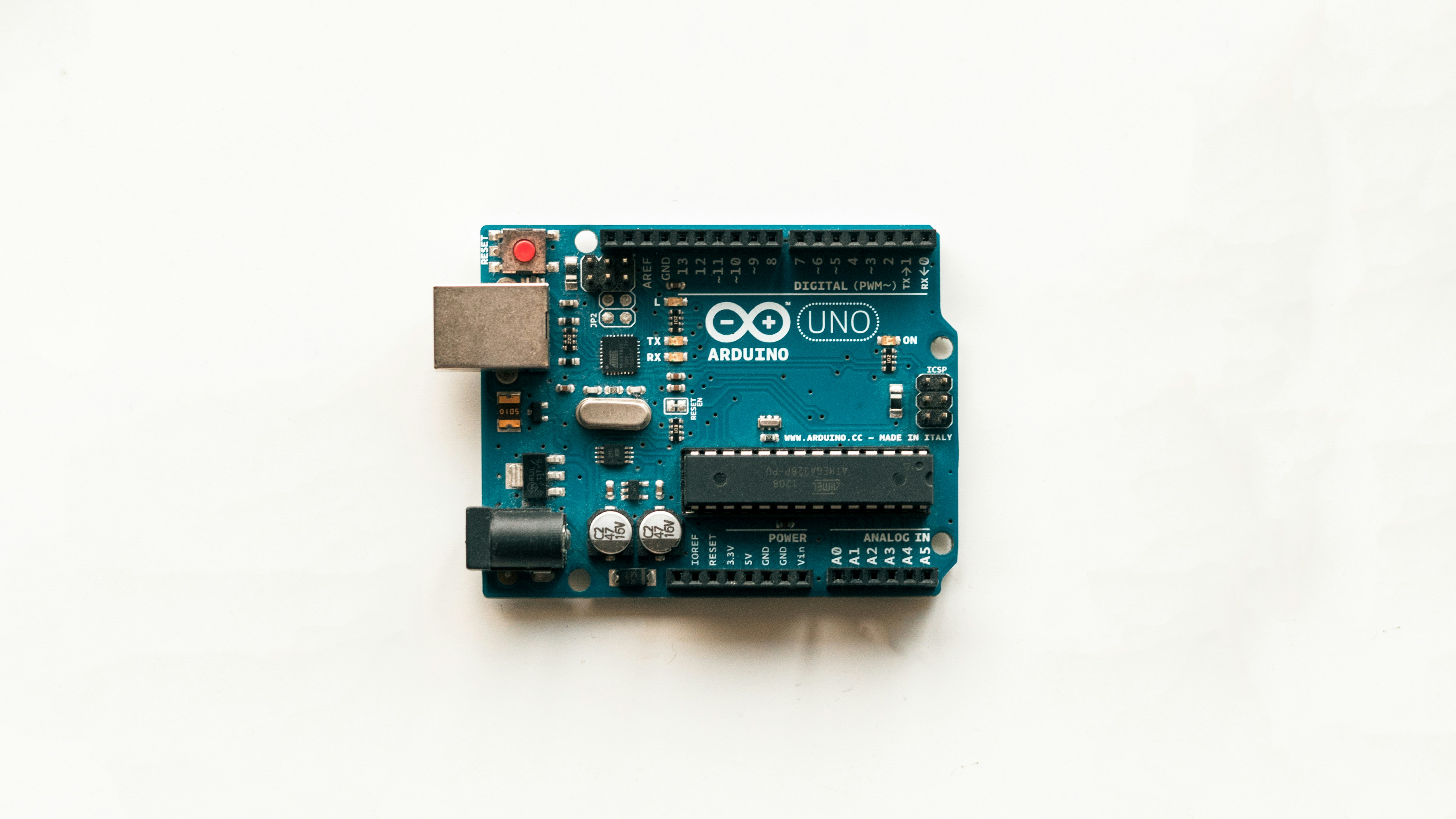
The story of moving things with code is as old as computing itself, but the Arduino revolution democratized it in a way no one saw coming. Before the mid-20s, if you wanted to make a robot move, you needed a degree in electrical engineering and a soldering iron the size of a baseball bat.
Enter the Arduino Uno and the Motor Shield Rev3. Suddenly, the barrier to entry dropped from “PhD in Robotics” to “High School Science Fair.” The L298 driver chip, which powers many of these shields, has been around since the 1980s, but pairing it with the accessible Arduino ecosystem turned it into a household name for makers.
We remember our first attempt at motor control back in the day. We tried to drive a motor directly from a digital pin. Spoiler alert: it didn’t work. The motor didn’t even twitch, and were left staring at a blinking LED wondering what we did wrong. It wasn’t until we learned about H-Bridges that the lightbulb went on. An H-Bridge is essentially four switches arranged in an ‘H’ shape that allows current to flow in either direction, enabling forward and reverse motion.
This evolution from raw, dangerous direct control to safe, shielded abstraction is what makes modern robotics so accessible. Today, you can control a stepper motor with millimeter precision or a DC motor with variable speed, all without building a single transistor circuit from scratch. But as we’ll see, “easy” doesn’t always mean “folproof.”
🧠 The Brain Behind the Brawn: Understanding Motor Control Fundamentals
So, you have a motor. It’s a beautiful piece of copper and plastic. But how do you tell it to move? This is where the magic of firmware meets the physics of electromagnetism.
The H-Bridge: The Heart of Direction
At the core of almost every motor control project is the H-Bridge. Think of it as a traffic cop for electricity.
- Forward: Current flows from Left to Right.
- Reverse: Current flows from Right to Left.
- Brake: Both sides are grounded (or both connected to VCC), stopping the motor instantly.
- Coast: Both sides are disconnected (floating), letting the motor spin down naturally.
Without an H-Bridge, you can only turn a motor on or off. With it, you have bidirectional control.
PWM: The Art of Speed Control
You might think, “If I want the motor to go half speed, I just give it half the voltage.” Wrong! Most motors don’t like variable voltage; they like Pulse Width Modulation (PWM).
PWM is like flicking a light switch on and off so fast that your eye (or the motor’s inertia) sees it as dim light (or slower speed). By changing the duty cycle (the percentage of time the signal is “on”), you control the average power delivered to the motor.
Did you know? The default PWM frequency on Arduino pins 3 and 1 is 980Hz, while others are 490Hz. This is why some motors hum louder than others!
Why You Need a Driver
You cannot connect a motor directly to an Arduino pin.
- Current: Arduino pins can handle ~40mA max. Motors need hundreds of mA or even Amps.
- Voltage: Arduino logic is 5V. Motors might need 12V.
- Protection: Motors generate electrical noise (EMI) that can reset your microcontroller.
This is why we use Motor Drivers or Shields. They act as the muscle, taking the tiny signals from the Arduino brain and amplifying them into the force needed to spin a wheel.
🔌 Choosing Your Champion: A Deep Dive into Motor Types for Arduino
Not all motors are created equal. Choosing the wrong one is like trying to win a drag race with a bicycle. Let’s break down the contenders.
1. DC Motors (Brushed)
The workhorses of the robotics world. Simple, cheap, and great for wheels.
- Pros: Easy to control (just PWM for speed, H-Bridge for direction), high torque at low speeds.
- Cons: Brushes wear out over time, less precise positioning.
- Best For: Robot cars, fans, conveyor belts.
2. Stepper Motors
The precision surgeons. They move in discrete steps.
- Pros: Incredible precision, hold position without power, no feedback loop needed for open-loop control.
- Cons: Low torque at high speeds, complex control, can overheat.
- Best For: 3D printers, CNC machines, camera sliders.
3. Servo Motors
The position masters. They have a built-in control circuit.
- Pros: Easy to control (just send a pulse width), hold position firmly, high torque for their size.
- Cons: Limited rotation (usually 180° or 360°), slower than DC motors.
- Best For: Robotic arms, steering mechanisms, camera gimbals.
Comparison Table: Which Motor Fits Your Project?
| Feature | DC Motor (Brushed) | Stepper Motor | Servo Motor |
|---|---|---|---|
| Control Complexity | Low (PWM + Direction) | High (Step/Dir signals) | Medium (Pulse Width) |
| Positioning Accuracy | Low (Needs Encoder) | High (Open Loop) | High (Closed Loop) |
| Speed Range | High | Low to Medium | Low to Medium |
| Torque at Low Speed | High | High | High |
| Cost | $ | $$ | $$ |
| Ideal Use Case | Locomotion | Precision Movement | Angled Positioning |
Pro Tip: If you need a robot to drive in a straight line, a DC motor with an encoder is often better than a stepper. Steppers are great for “move 10 steps,” but DC motors with encoders are better for “move 1 meter.”
🛠️ The Hardware Toolkit: Essential Shields, Drivers, and Modules
Now that you know what motor to use, let’s talk about how to drive it. The market is flooded with options, but we’ve tested them all so you don’t have to burn your house down.
The Official Contender: Arduino Motor Shield Rev3
This is the gold standard for beginners. It stacks directly on top of the Arduino Uno.
- Driver: L298P (Dual Full-Bridge).
- Channels: 2 DC motors or 1 Stepper.
- Current: 2A per channel, 4A total.
- Features: Current sensing, TinkerKit connectors, screw terminals.
👉 CHECK PRICE on:
- Amazon: Arduino Motor Shield Rev3
- Official Store: Arduino Store
The Budget King: L298N Module
You’ve seen this blue board with the giant heatsink. It’s everywhere.
- Pros: Cheap, robust, handles up to 2A per channel easily.
- Cons: Huge voltage drop (loses ~2V), gets hot, bulky.
- Verdict: Great for protyping, but inefficient for battery-powered projects.
The Modern Choice: TB612FNG
This is what we use when we need efficiency.
- Pros: Low voltage drop (only ~0.5V), runs cooler, smaller footprint, supports higher PWM frequencies.
- Cons: Slightly more expensive than L298N, requires a breakout board (doesn’t stack like the Rev3 shield).
- Verdict: The best choice for battery-operated robots.
Comparison: Driver IC Showdown
| Feature | L298 (Rev3 Shield) | L298N Module | TB612FNG |
|---|---|---|---|
| Max Current | 2A/ch | 2A/ch | 1.2A/ch (Peak 2A) |
| Voltage Drop | ~2.0V | ~2.0V | ~0.5V |
| Efficiency | Low | Low | High |
| Heat Generation | High | High | Low |
| PWM Freq | Limited by L298 | Limited by L298 | Up to 10kHz |
| Cost | Medium | Low | Medium |
Why the voltage drop matters: If you have a 12V battery and use an L298, your motor only sees ~10V. That’s a 16% loss in power! The TB612 gives you almost the full 12V.
🚀 Step-by-Step: Controlling a DC Motor with Motor Shield Rev3 and Beyond
Ready to make something move? Let’s walk through the process of controlling a DC motor using the Arduino Motor Shield Rev3. We’ll assume you have the shield, an Arduino Uno, and a small 6-12V DC motor.
Step 1: Hardware Assembly
- Stack the Shield: Gently push the Motor Shield Rev3 onto the Arduino Uno. Ensure all pins align.
- Power Check: If your motor is rated for >9V, cut the “Vin Connect” jumper on the back of the shield. This separates the motor power from the Arduino logic power.
- Connect Power: Plug your external battery pack (e.g., 2x 18650 Li-Ion cells) into the Vin and GND screw terminals. Do not rely on USB power!
- Connect Motor: Screw your motor wires into Channel A (or B) screw terminals. Polarity doesn’t matter yet; we can flip it in code.
Step 2: Understanding the Pinout
The Rev3 shield uses specific pins for a reason. Don’t try to use them for other things unless you cut the jumpers.
- Direction: Digital Pin 12 (Channel A), Digital Pin 13 (Channel B).
- Speed (PWM): Digital Pin 3 (Channel A), Digital Pin 1 (Channel B). Note: Pin 1 is unusual, but that’s the spec.
- Brake: Digital Pin 9 (Channel A), Digital Pin 8 (Channel B).
- Current Sense: Analog Pin A0 (Channel A), Analog Pin 1 (Channel B).
Step 3: The Code
Here is a simple sketch to spin the motor forward, brake, reverse, and coast.
// Pin Definitions for Channel A
const int dirPin = 12;
const int pwmPin = 3;
const int brakePin = 9;

void setup() {
 pinMode(dirPin, OUTPUT);
 pinMode(pwmPin, OUTPUT);
 pinMode(brakePin, OUTPUT);

 // Start with motor stopped
 digitalWrite(brakePin, HIGH); // Brake engaged
 digitalWrite(dirPin, LOW);
 analogWrite(pwmPin, 0);
}

void loop() {
 // 1. Move Forward
 digitalWrite(brakePin, LOW); // Release brake
 digitalWrite(dirPin, HIGH); // Set direction
 analogWrite(pwmPin, 150); // Speed (0-25)
 delay(20);

 // 2. Brake (Stop instantly)
 digitalWrite(brakePin, HIGH); // Engage brake
 delay(10);

 // 3. Move Reverse
 digitalWrite(brakePin, LOW);
 digitalWrite(dirPin, LOW); // Flip direction
 analogWrite(pwmPin, 150);
 delay(20);

 // 4. Coast (Slow stop)
 digitalWrite(brakePin, LOW); // Release brake
 analogWrite(pwmPin, 0); // Cut power
 delay(20);
}
Step 4: Testing and Tuning
Upload the code. If the motor spins backward, flip the wires or change the dirPin logic. If it doesn’t spin, check your external power. Remember: The motor needs a lot of current to start. If it just clicks, your battery is weak or the voltage is too low.
For more detailed tutorials on this specific setup, check out the official guide on Controlling a DC Motor with Motor Shield Rev3.
🌀 Mastering Precision: The Ultimate Guide to Stepper Motor Control
DC motors are great for going fast, but what if you need to move a camera lens exactly 0.5mm? Enter the Stepper Motor.
How Steppers Work
Unlike DC motors that spin continuously, stepper motors move in steps. A common NEMA 17 stepper has 20 steps per revolution (1.8° per step). By energizing the coils in a specific sequence, we can move the motor one step at a time.
The Library: AccelStepper
While you can write your own stepper code, it’s a nightmare. We highly recommend the AccelStepper library. It handles acceleration, deceleration, and multi-stepper synchronization automatically.
Wiring a Bipolar Stepper
Most hobby steppers are bipolar (4 wires).
- Identify the pairs: Use a multimeter to find which wires have continuity.
- Connect to the shield: The Arduino Motor Shield Rev3 has a specific header for steppers.
- Warning: Steppers draw constant current even when holding position. They get hot! Ensure your power supply can handle the current.
Code Example: Moving 10 Steps
# include <AccelStepper.h>

// Define pins for the shield (Channel A + B combined)
// Note: Pin mapping depends on how you wire the stepper to the shield
AccelStepper stepper(AccelStepper::DRIVER, 3, 12); // PWM, Dir

void setup() {
 stepper.setMaxSpeed(10);
 stepper.setAcceleration(50);
}

void loop() {
 if (stepper.distanceToGo() == 0) {
 stepper.moveTo(stepper.currentPosition() + 10); // Move 10 steps
 }
 stepper.run();
}
Why use AccelStepper? Without acceleration control, a stepper can miss steps if you tell it to start moving too fast. The library ramps up the speed smoothly, ensuring precision and reliability.
🤖 Servo Showdown: Achieving Exact Angular Positioning
Servos are the easiest motors to control, but they have a catch: they are limited in rotation (usually).
The Signal
Servos use a PWM signal but with a different timing.
- 1ms pulse: 0°
- 1.5ms pulse: 90° (Center)
- 2ms pulse: 180°
The Library: Servo.h
Arduino has a built-in library that makes this trivial.
# include <Servo.h>

Servo myServo;

void setup() {
 myServo.attach(9); // Attach to pin 9
 myServo.write(90); // Move to center
}

void loop() {
 for (int pos = 0; pos <= 180; pos += 1) {
 myServo.write(pos);
 delay(15);
 }
 for (int pos = 180; pos >= 0; pos -= 1) {
 myServo.write(pos);
 delay(15);
 }
}
Continuous Rotation Servos
Want a servo that spins like a wheel? You can modify a standard servo by removing the mechanical stop and replacing the potentiometer with a fixed resistor. This turns it into a continuous rotation servo, controlled by speed and direction rather than position.
Pro Tip: Servos draw a lot of current when they stall. If your Arduino resets when the servo moves, you need a separate power supply for the servo.
⚡️ Powering Up: Voltage, Current, and Battery Management Strategies
We can’t stress this enough: Power is the #1 cause of failure in motor projects.
Understanding the Numbers
- Voltage (V): The “pressure” pushing the current. Higher voltage = faster motor (usually).
- Current (A): The “flow” of electricity. This is what kills your board.
- Capacity (mAh): How long your battery lasts.
Battery Types for Robotics
- Li-Ion (18650): High energy density, 3.7V nominal. Great for portable robots.
Tip: Use a 2S (7.4V) or 3S (1.1V) pack for better speed. - LiPo (Lithium Polymer): Lightweight, high discharge rates. Perfect for drones.
Warning: NEVER puncture or overcharge a LiPo. They can catch fire. - NiMH (AA/AAA): Safe, easy to find, but heavy and lower voltage (1.2V per cell).
The Power Distribution Hack
Don’t daisy-chain your motors. Use a Power Distribution Board or heavy-gauge wires to connect your battery to the motor driver’s power input. Thin wires cause voltage drops, leading to brownouts.
Check out these power solutions:
- Amazon: LiPo Battery Charger
- Amazon: 18650 Battery Holder
📉 Taming the Noise: PWM, Speed Regulation, and Directional Logic
We mentioned PWM earlier, but let’s dive deeper into tuning it.
The Whine Problem
If your motor sounds like a jet engine, it’s because the PWM frequency is in the audible range (20Hz – 20kHz).
- Solution: Change the PWM frequency.
- How: You can modify the timer registers in the Arduino code. For example, changing Timer 1 to 31kHz moves the noise to the ultrasonic range.
Speed Regulation with Encoders
Open-loop control (just sending PWM) is inaccurate. If your robot hits a bump, it slows down, and your code doesn’t know.
- The Fix: Add an encoder to the motor shaft.
- The Logic: The encoder counts pulses. Your code compares the actual speed to the desired speed and adjusts the PWM automatically. This is called a PID Controller.
Example Scenario:
You want the robot to move at 50% speed.
- Encoder reads 40% speed.
- PID calculates error: +10%.
- PID increases PWM to 60%.
- Loop repeats until speed is stable.
This is how self-driving cars and advanced robots maintain precision.
🛡️ Safety First: Protecting Your Board from Back EMF and Overheating
We’ve all been there: you hear a pop, smell burning plastic, and realize you’ve fried your Arduino. Let’s prevent that.
Back EMF (Electromotive Force)
When a motor stops, the spinning coils generate a reverse voltage spike.
- The Fix: The L298 and TB612 chips have built-in flyback diodes to handle this. If you build your own H-bridge, you must add external diodes (like 1N401) across the motor terminals.
Overheating
The L298 chip gets hot.
- Symptoms: Motor slows down, chip feels too hot touch.
- Fix: Add a heatsink to the driver chip. If you’re pushing 2A continuously, consider a fan or a more efficient driver like the TB612.
Short Circuit Protection
If you accidentally cross the motor wires, the driver might short.
- Prevention: Use fuses in your power line. A 3A fuse will blow before your wires melt.
🧪 Real-World Projects: From Line Followers to Robotic Arms
Theory is great, but let’s build something cool.
Project 1: The Line Follower
- Motors: 2x DC Motors with encoders.
- Sensors: 3x IR sensors.
- Logic: If the middle sensor sees black, go straight. If the left sees black, turn left. Use PID to smooth the turns.
- Why it works: It teaches you sensor fusion and closed-loop control.
Project 2: The Robotic Arm
- Motors: 4x Servo motors.
- Logic: Inverse kinematics to calculate angles for the gripper to reach a point.
- Challenge: Servos have limited torque. You need to balance the arm or use high-torque servos.
Project 3: The Self-Balancing Robot
- Motors: 2x DC Motors.
- Sensor: MPU6050 (Accelerometer + Gyro).
- Logic: A complex PID loop that constantly adjusts motor speed to keep the robot upright.
- Difficulty: Hard! But incredibly rewarding.
For more inspiration, check out our articles on Robotics and Robotic Simulations.
🐞 Troubleshooting Tangles: Why Your Motor Won’t Spin (And How to Fix It)
Nothing is more frustrating than a motor that refuses to move. Here is our diagnostic checklist:
- Check the Power: Is the battery dead? Is the external power connected to the Vin terminal? (USB won’t work).
- Check the Jumper: Did you cut the “Vin Connect” jumper if using >9V?
- Check the Pins: Are you using the correct pins for PWM and Direction? (e.g., Pin 3 for PWM, Pin 12 for Dir).
- Check the Code: Is the
brakePinset to HIGH? (This stops the motor). - Check the Motor: Is the motor burnt out? Test it with a battery directly (carefully!).
- Check the Driver: Is the chip hot? Did it overheat?
Common Mistake: Confusing Channel A and Channel B pins in the code. If you define dirPin = 12 but wire the motor to Channel B, nothing will happen.
💡 Pro Tips, Hidden Gems, and Common Pitfalls
We’ve learned these the hard way, so you don’t have to.
- Tip 1: Use
analogReadfor Current Sensing. Monitor the current on A0/A1. If it spikes, stop the motor immediately to prevent damage. - Tip 2: Debounce Your Switches. If you use buttons to control direction, add a small delay or software debounce to prevent “bouncing” (rapid on/off).
- Tip 3: Don’t Forget the Ground. Ensure your Arduino, motor driver, and power supply share a common ground. Without it, the signals won’t work.
- Pitfall: Using
delay()in your main loop. This freezes your robot. Usemillis()for non-blocking code. - Hidden Gem: The TinkerKit connectors on the Rev3 shield. They make it super easy to connect sensors without soldering.
Watch this video for a visual guide on the shield’s layout and common mistakes:
Featured Video: Understanding the Arduino Motor Shield
“First off, a shield is something that goes directly onto a microcontroller. This is very important. Otherwise you might burn your board.”
This simple advice from the video sums up the importance of understanding the hardware stack.
Conclusion
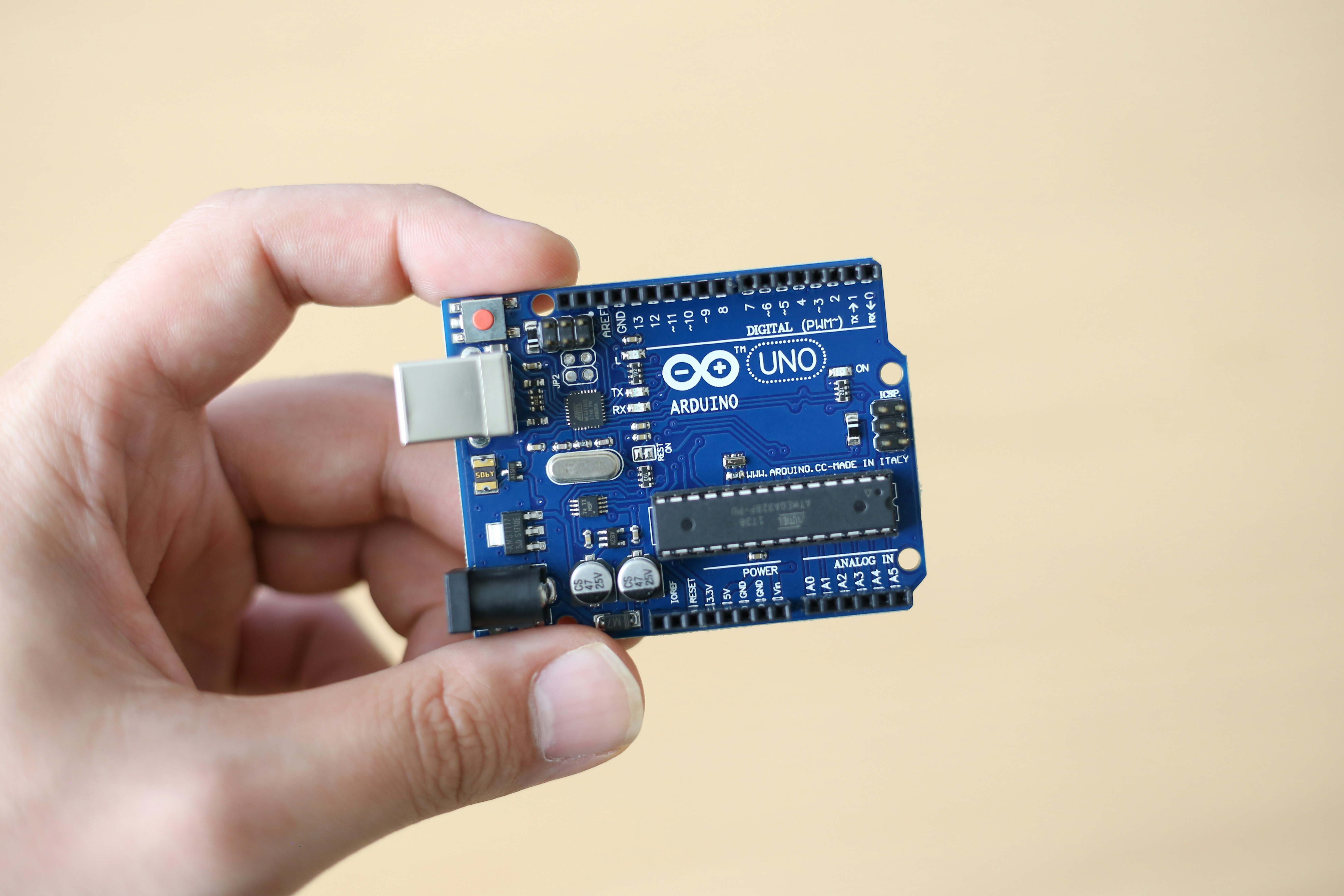
We’ve journeyed from the basics of H-Bridges to the complexities of PID control and stepper precision. The world of Arduino motor control is vast, but with the right tools and knowledge, it’s entirely within your reach.
Our Verdict:
If you are a beginner, start with the Arduino Motor Shield Rev3. It’s robust, well-documented, and teaches you the fundamentals of current sensing and braking. However, if you are building a battery-powered robot where efficiency matters, switch to a TB612FNG driver. It runs cooler and gives you more power.
Positives of the Arduino Motor Shield Rev3:
- ✅ Easy to use (stackable).
- ✅ Built-in current sensing.
- ✅ Open-source hardware (schematics available).
- ✅ Supports both DC and Stepper motors.
Negatives:
- ❌ L298P chip is inefficient (high voltage drop).
- ❌ Gets hot under load.
- ❌ Pin 1 usage for PWM is non-standard.
Final Recommendation:
Don’t be afraid to experiment. Start with a simple DC motor, get it spinning, then add an encoder, then a PID loop. The path to mastery is paved with burnt components and code errors. Embrace the chaos, and soon you’ll be building robots that can navigate the world with precision.
Ready to build? Grab your components and start coding. The future of robotics is in your hands!
📚 Recommended Links
Essential Hardware:
- Arduino Motor Shield Rev3: Amazon | Official Store
- L298N Motor Driver Module: Amazon
- TB612FNG Motor Driver: Amazon
- NEMA 17 Stepper Motor: Amazon
- High Torque Servo Motor: Amazon
Books & Resources:
- Make: Arduino Bots and Gadgets by Kimo Karvinen – Amazon
- Robotics with the Arduino by Simon Monk – Amazon
❓ Frequently Asked Questions (FAQ)
How do I control a DC motor with Arduino using an L298N motor driver?
To control a DC motor with an L298N, you need to connect the motor to the output terminals (OUT1 and OUT2). Connect the ENA pin to a PWM pin on the Arduino for speed control, and IN1 and IN2 to digital pins for direction. Set ENA to HIGH to enable the motor, then use analogWrite() on the PWM pin to control speed. To reverse direction, swap the logic on IN1 and IN2. Crucial: Always use an external power source for the motor; the L298N cannot be powered solely by the Arduino’s 5V pin for high-current motors.
What is the best PWM frequency for Arduino motor control?
The default PWM frequency on most Arduino pins is 490Hz or 980Hz. This is often audible as a whine. For quieter operation, you can increase the frequency to 31kHz or higher by modifying the timer registers. However, be aware that some motor drivers (like the L298) have a maximum frequency limit (usually around 20-30kHz). If you go too high, the motor might not respond correctly. For most applications, 20kHz is a good balance between silence and performance.
Read more about “🤖 Master MicroPython Robotics: 7-Step Tutorial for 2026”
How can I control the speed of a stepper motor with Arduino?
You cannot control the speed of a stepper motor with simple PWM. Instead, you control the step rate (steps per second). The AccelStepper library is the standard tool for this. You set the setMaxSpeed() and setAcceleration() values, and the library handles the timing of the pulses sent to the driver. To change speed dynamically, you simply call stepper.setSpeed(newSpeed) or stepper.moveTo(targetPosition).
Read more about “10 Best Arduino Programming Tutorials to Master Robotics (2026) 🤖”
Can I use Arduino to control multiple motors simultaneously?
Yes, absolutely. The Arduino Uno has enough digital pins to control 2 DC motors (using the Motor Shield) or even 4+ motors with individual drivers. The key is to ensure your power supply can handle the total current draw of all motors running at once. Also, if you are using servos, be aware that the Servo library can interfere with PWM on certain pins. Using a dedicated motor driver board or shield is the best way to manage multiple motors.
How do I reverse the direction of a motor using Arduino code?
Reversing direction depends on the motor type:
- DC Motor: Swap the logic on the direction pins. If
digitalWrite(dirPin, HIGH)is forward, thendigitalWrite(dirPin, LOW)is reverse. - Stepper Motor: Change the sign of the step count or use
stepper.moveTo(-currentPosition)to reverse direction. - Servo Motor: If it’s a continuous rotation servo, reverse the pulse width (e.g., 1ms forward, 2ms for reverse). If it’s a standard servo, you can’t “reverse” it; you just move it to the opposite angle.
Read more about “🤖 7 Arduino Robotics Projects to Master Coding Skills (2026)”
What is the difference between a servo motor and a DC motor in Arduino projects?
A DC motor spins continuously and is controlled by speed (PWM) and direction. It requires an external encoder for precise positioning. A servo motor has a built-in control circuit and moves to a specific angle (0-180°) based on a pulse width signal. Servos are easier to control for positioning but are limited in rotation and speed. DC motors are better for locomotion (wheels), while servos are better for joints and arms.
Read more about “🤖 15+ Best Arduino Sensors for Robots (2026 Guide)”
How do I add encoders to my Arduino motor control setup for feedback?
To add encoders, you need a motor with an encoder disk or a separate encoder module. Connect the encoder’s output pins (A and B) to the Arduino’s interrupt-capable pins (like 2 and 3 on the Uno). Use a library like Encoder.h to count the pulses. In your code, read the encoder value and compare it to your target speed. If the actual speed is lower than desired, increase the PWM. This creates a closed-loop system that maintains consistent speed regardless of load.
🔗 Reference Links
- Arduino Official Documentation: Controlling a DC Motor with Motor Shield Rev3
- Arduino Motor Shield Rev3 Product Page: Arduino Store
- L298 Datasheet: STMicroelectronics
- TB612FNG Datasheet: Toshiba
- AccelStepper Library: Aberdeen University
- Servo Library Reference: Arduino.cc
- PID Control Basics: Control Systems Engineering
- Robotic Coding™: Arduino Guide: Arduino Overview
- Robotic Coding™: Robotics Category: Robotics
- Robotic Coding™: Coding Languages: Coding Languages