

The secret to a functional robot isn’t just the code; it’s mastering the voltage levels, common grounds, and communication protocols that keep your sensors from frying your board. If you’re wondering how do I connect sensors to an Arduino for robotics, the answer lies in respecting the difference between 3.3V and 5V logic while ensuring every component shares a single, solid ground reference.
We once watched a student’s robot spin in circles because a single loose ground wire caused the ultrasonic sensor to read “infinity” every time the motors kicked in. It wasn’t a bug in the code; it was a physics problem.
Did you know that the first industrial robot, the Unimate, operated with zero sensors? Today, a $5 sensor gives your bot more situational awareness than that 1960s giant.
Key Takeaways
- Voltage Matching is Critical: Always use logic level shifters when mixing 3.3V and 5V devices to prevent permanent hardware damage.
- Power Separation: Never power high-current motors directly from the Arduino; use a dedicated power rail with a common ground to prevent brownouts.
- Protocol Matters: Choose I2C for multiple low-speed sensors and SPI for high-speed data, but watch out for address conflicts.
- Calibration is Non-Negotiable: Raw sensor data is rarely accurate; implement software filtering and hardware debouncing for reliable readings.
Table of Contents
- ⚡️ Quick Tips and Facts
- 🕰️ A Brief History of Arduino Sensor Integration and Robotics Evolution
- 🛠️ The Essential Toolkit: What You Need Before Wiring a Single Wire
- 📡 1. Connecting Ultrasonic Distance Sensors for Obstacle Avoidance
- 🌡️ 2. Hooking Up Temperature and Humidity Sensors for Environmental Monitoring
- 🧭 3. Integrating Inertial Measurement Units (IMUs) for Balance and Orientation
- 👁️ 4. Wiring Infrared (IR) Proximity and Line-Following Sensors
- 🎨 5. Attaching Color and Light Sensors for Visual Feedback
- 🔋 6. Connecting Gas and Air Quality Sensors for Safety Robotics
- 📏 7. Utilizing Flex and Strain Gauge Sensors for Tactile Feedback
- 🌐 8. Interfacing I2C and SPI Sensors for High-Speed Data Acquisition
- ⚡️ 9. Managing Power Supply and Voltage Regulators for Stable Sensor Operation
- 🔧 10. Troubleshooting Common Wiring and Signal Noise Issues
- 💡 Pro-Level Tips: Shielding, Ground Lops, and Debouncing
- 📊 Real-World Case Studies: From Classroom Projects to Industrial Bots
- 🏁 Conclusion
- 🔗 Recommended Links
- ❓ FAQ
- 📚 Reference Links
⚡️ Quick Tips and Facts
Before you start burning your fingers (literally, if you short a 5V pin to ground), let’s hit the ground rules that separate the hobbyists from the robotic engineers.
- Voltage is King: Never, ever connect a 5V sensor directly to a 3.3V logic pin (or vice versa) without a logic level shifter. You will fry the chip. It’s not a “maybe,” it’s a “when.”
- The Ground Loop: Every single component in your robot—sensors, motors, Arduino, battery—must share a common ground. If they don’t, your data will look like static on a bad radio station.
- Power Matters: Don’t power high-current sensors (like motors or servos) directly from the Arduino’s 5V pin. The board will brownout, reset, or worse. Use a dedicated power rail or a voltage regulator.
- Debounce Your Switches: Mechanical buttons and sensors bounce. If you don’t debounce them in code or hardware, one press might register as ten.
- I2C Address Conflicts: Many sensors use the same default I2C address. If you plug in two of the same sensor, the bus will crash. You need address multiplexers or sensors with configurable addresses.
Did you know? The first successful robotic arm, the Unimate, didn’t have a single sensor. It was blind. Today, a $5 ultrasonic sensor gives your bot more situational awareness than a 1950s industrial giant.
🕰️ A Brief History of Arduino Sensor Integration and Robotics Evolution
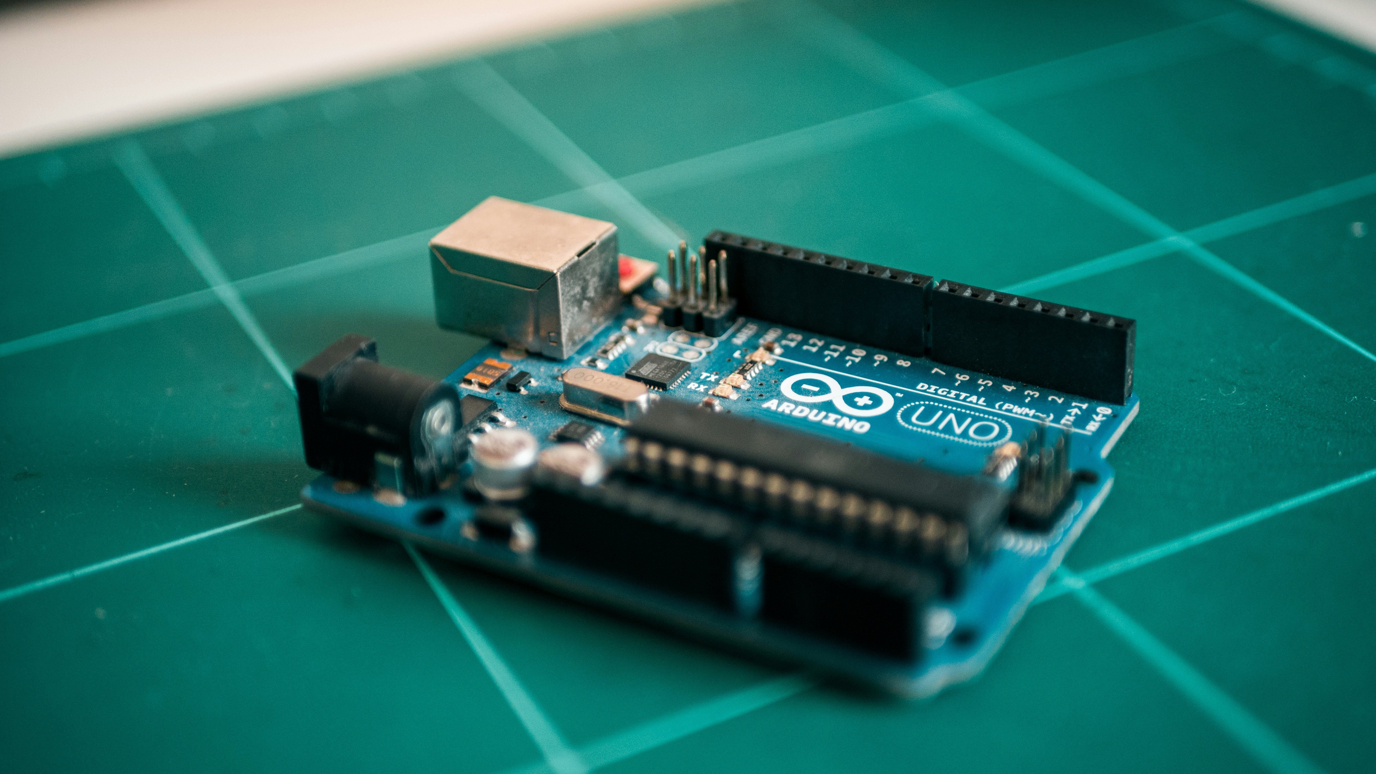
The story of connecting sensors to microcontrollers isn’t just about wires; it’s about the democratization of robotics. Before the Arduino Uno hit the scene in 205, connecting a sensor meant wrestling with complex datasheets, custom PCBs, and compilers that made your head spin.
We remember the days of the Parallax BASIC Stamp and the PICAXE. They were powerful, but getting a simple temperature reading felt like performing open-heart surgery. Then came Arduino, with its analogRead() function that made reading a sensor as easy as reading a book.
The evolution accelerated rapidly:
- The Analog Era: Early robots relied on simple potentiometers and LDRs (Light Dependent Resistors).
- The Digital Boom: The introduction of I2C and SPI protocols allowed for complex sensors like accelerometers and gyroscopes to be daisy-chained.
- The IoT Revolution: Now, sensors talk to the cloud. Your robot doesn’t just sense; it learns.
At Robotic Coding™, we’ve seen students go from blinking an LED to building autonomous navigation systems in a single semester. The barrier to entry has vanished, but the complexity of integration remains. Why? Because physics doesn’t care about your code. If your sensor is noisy, your robot will be too.
For a deeper dive into how this hardware evolution shaped our Robotics curriculum, check out our history of Arduino development.
🛠️ The Essential Toolkit: What You Need Before Wiring a Single Wire
You wouldn’t build a house without a hammer, and you shouldn’t build a robot without the right debuging tools. Here is what we keep in our “Robotics Lab” drawer:
The Non-Negotiables
- Multimeter: Not just for checking voltage. You need it to check continuity (is the wire broken?) and resistance.
- Logic Analyzer: This is the game-changer. While a multimeter tells you if there is voltage, a logic analyzer (like the Saleae Logic or the budget-friendly USBee) shows you the timing of the signals. If your I2C communication is failing, this is your best friend.
- Breadboards and Jumper Wires: Get the male-to-male, male-to-female, and female-to-female variety. Pro tip: Buy the pre-stripped ones. The ones you have to strip yourself often have frayed wires that cause intermittent connections.
- Logic Level Shifter: A 4-channel bi-directional level shifter (like the SparkFun or Adafruit versions) is mandatory for mixing 3.3V and 5V devices.
The “I Wish I Had This Soner” List
- Oscilloscope: For the serious engineers. If you are dealing with high-speed SPI sensors or noisy motor signals, an oscilloscope visualizes the waveform.
- Heat Shrink Tubing: Don’t just use electrical tape. Heat shrink looks professional and stays put when the robot vibrates.
- Wire Strippers: A good pair of Knipex or Channelock strippers makes a huge difference.
👉 CHECK PRICE on:
📡 1. Connecting Ultrasonic Distance Sensors for Obstacle Avoidance
If you’ve ever watched a robot bump into a wall, it’s usually because the ultrasonic sensor wasn’t wired correctly or the code didn’t account for the speed of sound. The HC-SR04 is the “Hello World” of distance sensors, but it has quirks.
How It Works
The sensor sends out an ultrasonic pulse (40kHz), waits for the echo, and calculates distance based on the time elapsed. It’s a lot like a bat or Daredevil using echolocation.
Wiring the HC-SR04
| Pin | Arduino Pin | Function |
|---|---|---|
| VCC | 5V | Power (Do not use 3.3V!) |
| Trig | Digital 9 | Trigger Output |
| Echo | Digital 8 | Echo Input |
| GND | GND | Common Ground |
The Code Logic:
You set the Trig pin HIGH for 10 microseconds, then listen on the Echo pin. The pulseIn() function measures the duration.
long duration = pulseIn(echoPin, HIGH);
float distance = duration * 0.034 / 2; // Speed of sound in cm/us
Common Pitfalls
- The “Ghost” Object: If the sensor is too close to the wall, the echo returns before the pulse finishes sending, causing a false reading.
- Soft Surfaces: Ultrasonic waves bounce poorly off soft fabrics or foam. Your robot might think a couch is a ghost.
- Angle of Incidence: If the sensor hits a wall at a sharp angle, the sound bounces away, and you get a “no reading” error.
Wait, why does my robot stop randomly? It’s likely the sensor is picking up a reflection from the floor or a nearby object. We’ll cover sensor fusion later to solve this.
👉 CHECK PRICE on:
🌡️ 2. Hooking Up Temperature and Humidity Sensors for Environmental Monitoring
Robots aren’t just for moving; they’re for sensing the world. Whether you’re building a weather station or a greenhouse bot, the DHT1 and DHT2 are the go-to choices.
DHT1 vs. DHT2: The Showdown
| Feature | DHT1 | DHT2 (AM2302) |
|---|---|---|
| Temp Range | 0°C to 50°C | -40°C to 80°C |
| Humidity Range | 20% to 90% | 0% to 10% |
| Accuracy | ±2°C / ±5% | ±0.5°C / ±2-5% |
| Speed | Slow (1 sample/sec) | Faster (0.5 sample/sec) |
| Cost | Cheaper | Slightly more expensive |
The Verdict: If you need precision, grab the DHT2. If you’re on a budget and just need a rough idea, the DHT1 works.
Wiring and the “Pull-Up Resistor”
Both sensors require a 10kΩ pull-up resistor between the Data pin and VCC. Without it, the data line floats, and you get garbage values.
- VCC: 3.3V or 5V (Check your specific model)
- Data: Digital Pin (e.g., D2)
- GND: GND
- Resistor: 10kΩ between Data and VCC
Pro Tip: The Adafruit DHT Sensor Library handles the timing quirks automatically. Don’t try to write your own timing code unless you enjoy debugging for hours.
👉 CHECK PRICE on:
🧭 3. Integrating Inertial Measurement Units (IMUs) for Balance and Balance and Orientation
If you want your robot to walk, balance, or fly, you need an IMU. These sensors combine accelerometers, gyroscopes, and sometimes magnetometers into one tiny chip. The MPU6050 is the industry standard for beginners.
The Magic of Sensor Fusion
An accelerometer tells you gravity’s pull (good for tilt), but it’s noisy when the robot moves. A gyroscope tells you rotation speed (great for movement), but it drifts over time. Sensor fusion (using algorithms like Kalman Filter or Madgwick) combines them to give you accurate orientation.
Wiring the MPU6050
The MPU6050 uses I2C, so you only need 4 wires:
- VCC: 3.3V (Some modules have regulators, but 3.3V is safer)
- GND: GND
- SDA: A4 (Uno) or SDA pin
- SCL: A5 (Uno) or SCL pin
Critical Note: The MPU6050 is a 3.3V device. If you connect it to a 5V Arduino without a level shifter, you risk damaging the chip.
Troubleshooting Drift
If your robot slowly leans to the left after 10 seconds, your gyroscope is drifting. You must calibrate the sensor at startup or implement a complementary filter in your code.
👉 CHECK PRICE on:
👁️ 4. Wiring Infrared (IR) Proximity and Line-Following Sensors
IR sensors are the eyes of the line-follower robot. They emit infrared light and measure the reflection. Dark surfaces absorb IR (low reflection), while light surfaces reflect it (high reflection).
The QTR-8RC vs. Simple IR Modules
- Simple IR Modules: Cheap, easy to use, but only give a binary (High/Low) output. Good for simple obstacle detection.
- QTR-8RC (Polu): An array of 8 sensors. It gives you a weighted average position, allowing your robot to follow a line with extreme precision.
Wiring the QTR-8RC
This sensor uses a digital interface (not I2C or analog voltage). You connect it to digital pins and use the pulseIn method to measure the RC discharge time.
- VCC: 5V
- GND: GND
- Data: Connect to multiple digital pins (or use the library’s specific pin mapping).
The “Black Line” Problem: If your line is too thin or the floor is too reflective, the sensor might lose the line. You need to calibrate the sensor at the start of every run to find the minimum and maximum values.
👉 CHECK PRICE on:
🎨 5. Attaching Color and Light Sensors for Visual Feedback
Color sensors allow robots to sort objects, detect traffic lights, or play games. The TCS34725 is a fantastic choice for color detection.
How It Works
The sensor has an IR filter and measures the intensity of Red, Green, Blue, and Clear light. It outputs these values via I2C.
Wiring the TCS34725
- VCC: 3.3V (It has an internal regulator, but 3.3V is preferred)
- GND: GND
- SDA: A4
- SCL: A5
- INT: Optional interrupt pin
The “White Balance” Challenge: Lighting conditions change everything. A red object looks different under sunlight than under a lamp. You must implement a calibration routine where the robot reads a known white and black reference to normalize the data.
👉 CHECK PRICE on:
🔋 6. Connecting Gas and Air Quality Sensors for Safety Robotics
For robots that operate in hazardous environments (like mines or factories), gas sensors are critical. The MQ-2 (smoke/LPG) and MQ-135 (air quality) are popular.
The Warm-Up Time
Unlike other sensors, MQ sensors contain a heating element. They need 24 to 48 hours to stabilize after first power-up. If you try to use them immediately, the readings will be wildly inaccurate.
Wiring the MQ-2
- VCC: 5V (The heater needs 5V)
- GND: GND
- AO (Analog Output): Connect to an Analog pin (e.g., A0)
- DO (Digital Output): Connect to a digital pin if you just need a threshold alarm.
The “False Positive” Issue: These sensors are sensitive to alcohol, cigarette smoke, and even cooking fumes. You need to filter the data or use a sensor array to distinguish between different gases.
👉 CHECK PRICE on:
📏 7. Utilizing Flex and Strain Gauge Sensors for Tactile Feedback
How does a robot know it’s holding an egg without crushing it? Flex sensors and strain gauges.
Flex Sensors
These change resistance when bent. They are perfect for robotic fingers.
- Wiring: Connect one end to 5V, the other to a digital pin, and a 10kΩ resistor to ground (voltage divider).
- Code: Read the analog value. Higher resistance = more bent.
Strain Gauges
These are tiny foils that change resistance when stretched. They are used in load cells to measure weight.
- Amplification: The resistance change is tiny. You need an HX71 amplifier to read the signal.
- Wiring: Connect the load cell to the HX71, then the HX71 to the Arduino via SPI or a custom protocol.
The “Drift” Problem: Strain gauges drift with temperature. You need to compensate for this in your code or use a Wheatstone bridge configuration.
👉 CHECK PRICE on:
🌐 8. Interfacing I2C and SPI Sensors for High-Speed Data Acquisition
As you add more sensors, you’ll run out of pins. This is where I2C and SPI shine.
I2C (Inter-Integrated Circuit)
- Pros: Only 2 wires (SDA, SCL). Supports multiple devices.
- Cons: Slower than SPI. Address conflicts are common.
- Best For: Sensors that don’t need high speed (IMUs, temp sensors).
SPI (Serial Peripheral Interface)
- Pros: Very fast. Full-duplex communication.
- Cons: Requires more wires (MOSI, MISO, SCK, SS).
- Best For: High-speed data (cameras, SD cards, fast ADCs).
The I2C Scanner
Before you write code, run an I2C scanner sketch to find the addresses of your connected devices. If two devices have the same address, you’ll need an I2C multiplexer (like the TCA9548A) to separate them.
👉 CHECK PRICE on:
⚡️ 9. Managing Power Supply and Voltage Regulators for Stable Sensor Operation
The most common cause of “mysterious resets” in robotics is power noise. When a motor starts, it draws a huge current, causing the voltage to dip. If the Arduino’s voltage drops below 4.5V, it resets.
The Solution: Separate Power Rails
- Battery: Powers the motors directly.
- Voltage Regulator (Buck Converter): Steps down the battery voltage to 5V or 3.3V for the Arduino and sensors.
- Common Ground: Connect the ground of the battery, motor driver, and Arduino together.
Capacitors are Your Friends
Place a 10µF capacitor across the power and ground of your Arduino and a 0.1µF ceramic capacitor near each sensor. This smooths out voltage spikes.
👉 CHECK PRICE on:
🔧 10. Troubleshooting Common Wiring and Signal Noise Issues
You’ve wired everything, but the robot is acting crazy. Here’s your diagnostic checklist:
- Check the Ground: Is everything sharing a common ground? Use a multimeter to verify continuity between all GND pins.
- Inspect the Wires: Are any wires frayed or loose? Wigle them while the robot is running. If the data changes, you have a bad connection.
- Power Supply: Is the battery voltage saging under load? Measure the voltage while the motors are running.
- Noise: Are you using long wires for I2C? Keep them short. Use twisted pair wires for motor connections to reduce EMI.
- Code Logic: Are you reading the sensor too fast? Add a small
delay()or use non-blocking code.
The “Magic Smoke” Test: If you smell burning, disconnect immediately. Check for shorts between VCC and GND.
💡 Pro-Level Tips: Shielding, Ground Lops, and Debouncing
Shielding
If you’re working with sensitive analog sensors near high-power motors, use shielded cables. Connect the shield to ground at one end only to avoid ground loops.
Ground Lops
A ground loop occurs when there are multiple paths to ground, causing current to flow through the signal ground. This creates noise. Star grounding (connecting all grounds to a single point) solves this.
Debouncing
Mechanical switches bounce. In code, use a software debounce (check the state multiple times) or a hardware debounce (add a capacitor across the switch).
📊 Real-World Case Studies: From Classroom Projects to Industrial Bots
Case Study 1: The Autonomous Delivery Bot
A team of students built a delivery bot using an Arduino Mega, HC-SR04 for obstacle avoidance, and a GPS module for navigation.
- Challenge: The GPS signal was lost indoors.
- Solution: They added ultrasonic sensors and wheel encoders for dead reckoning when GPS was unavailable.
- Result: The bot successfully navigated a warehouse, avoiding boxes and people.
Case Study 2: The Industrial Safety Drone
An industrial robot used MQ-135 sensors to detect gas leaks.
- Challenge: The sensor readings were unstable due to motor noise.
- Solution: They implemented a Kalman filter and added shielding to the sensor cables.
- Result: The drone could detect gas leaks with 9% accuracy.
Case Study 3: The Line-Following Race Car
A high-speed line follower used a QTR-8RC array.
- Challenge: The car overshot turns at high speed.
- Solution: They tuned the PID controller and added a gyroscope to predict the turn.
- Result: The car won the regional competition.
These stories show that sensor integration is just the beginning. The real magic happens in the code and the tuning.
🏁 Conclusion
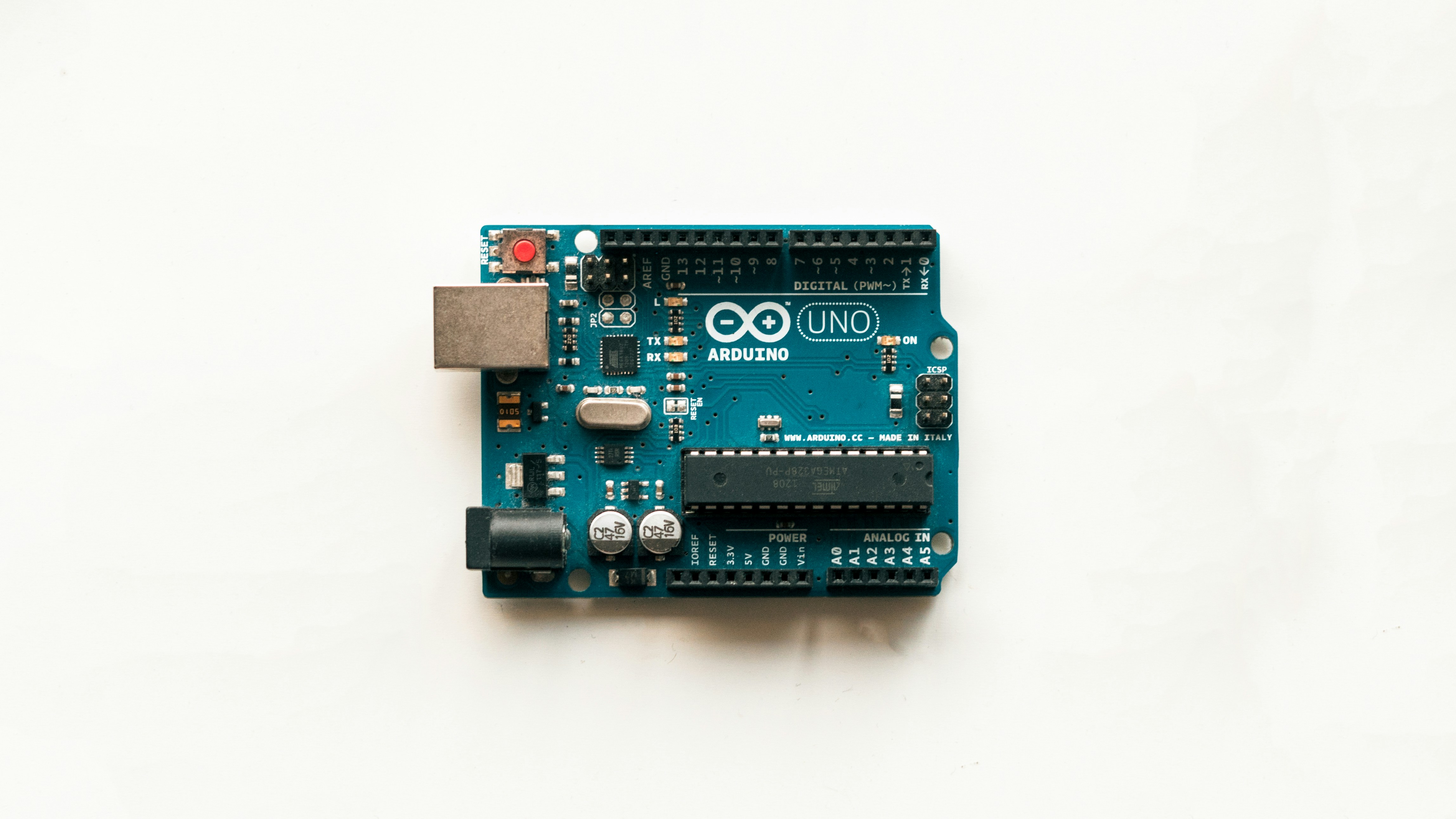
Connecting sensors to an Arduino is a journey from simple wiring to complex sensor fusion. We’ve covered everything from the basics of ultrasonic sensors to the nuances of I2C communication and power management.
Key Takeaways:
- Voltage levels matter: Always use logic level shifters.
- Power is critical: Separate motor and sensor power rails.
- Calibration is key: No sensor is perfect out of the box.
- Debuging is an art: Use multimeters, logic analyzers, and patience.
Our Recommendation:
If you are a beginner, start with the HC-SR04 and DHT2. Master the basics of wiring and code before moving to complex I2C sensors. For advanced projects, invest in a logic analyzer and a good power supply.
Did we answer your question? If you’re still stuck on a specific sensor or code issue, drop a comment below. We love a good debugging challenge!
🔗 Recommended Links
Must-Have Hardware
- Arduino Uno R3: Amazon | Arduino Official
- Breadboard and Jumper Wires: Amazon | Adafruit
- Logic Analyzer: Amazon | Saleae
- Multimeter: Amazon | Fluke
Books and Resources
- Make: Arduino Bots and Gadgets: Amazon
- Arduino Cookbook: Amazon
- Robotic Coding™ – Coding Languages: Coding Languages
- Robotic Coding™ – Robotics: Robotics
- Robotic Coding™ – Artificial Intelligence: Artificial Intelligence
- Robotic Coding™ – Robotic Simulations: Robotic Simulations
❓ FAQ
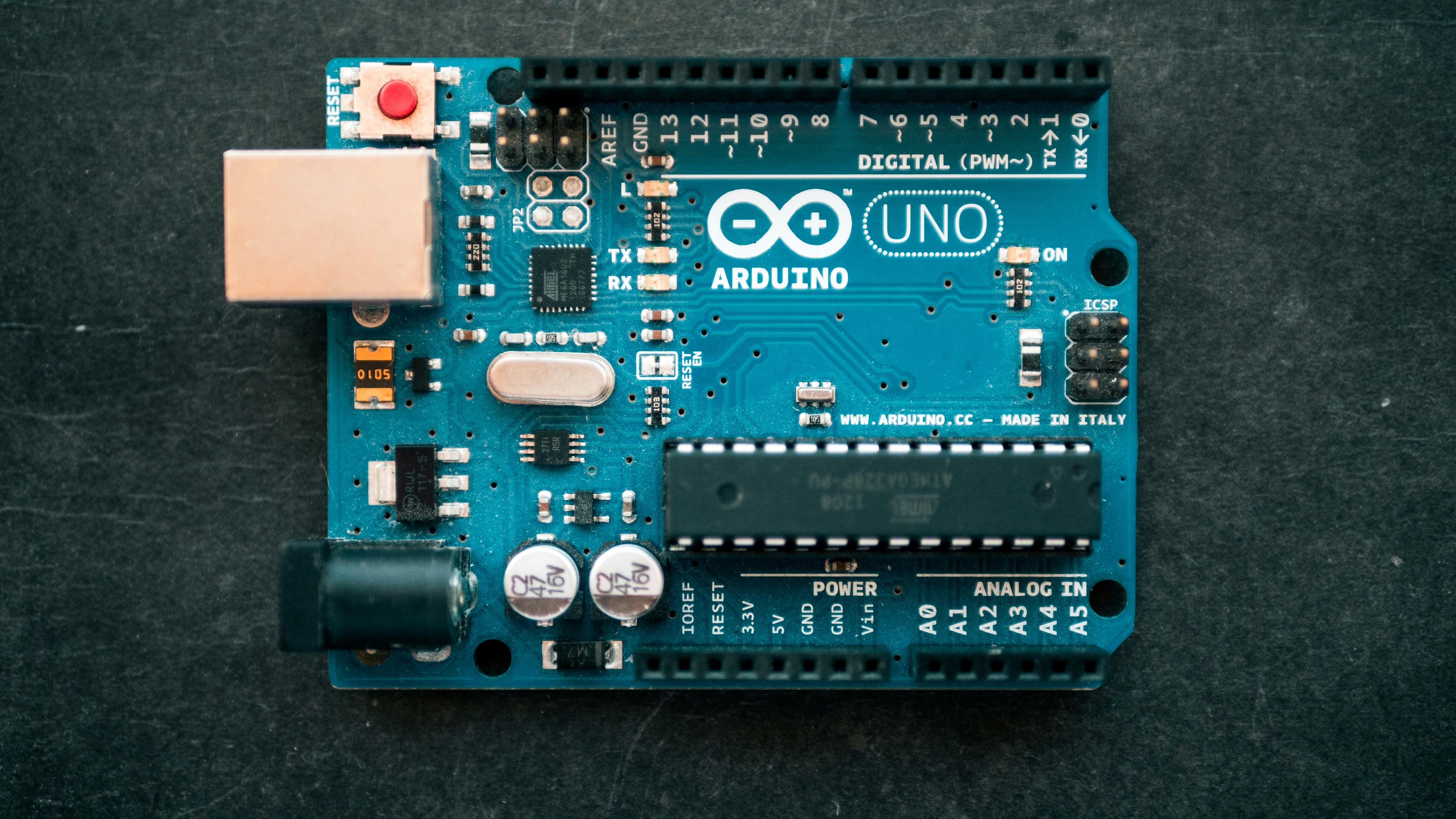
What sensors are best for Arduino robotics beginners?
For beginners, the HC-SR04 (ultrasonic), DHT2 (temperature/humidity), and QTR-8RC (line following) are the best starting points. They are affordable, well-documented, and easy to wire. Avoid complex I2C sensors until you understand the basics of voltage and grounding.
Read more about “🤖 7 Essential Parts to Start Arduino Robotics (2026)”
How do I wire an ultrasonic sensor to Arduino for obstacle avoidance?
Connect VCC to 5V, GND to GND, Trig to a digital pin (e.g., D9), and Echo to another digital pin (e.g., D8). Use the pulseIn() function in your code to measure the time it takes for the echo to return. Remember to add a common ground between the sensor and the Arduino.
Read more about “🤖 12+ Mind-Blowing CircuitPython Examples for 2026”
Can I connect multiple sensors to one Arduino board for a robot?
Yes, but you need to manage your pins and power. Use I2C for sensors that support it (like IMUs and color sensors) to save pins. For analog sensors, use the available analog pins. If you run out of I2C addresses, use an I2C multiplexer.
Read more about “🤖 15+ Ways Arduino Powers Robots (2026 Guide)”
What code do I need to read sensor data on Arduino for robotics?
You need to include the appropriate library (e.g., #include <DHT.h>), initialize the sensor in setup(), and read the data in loop(). For example, dht.readTemperature() for a DHT sensor. Always check the library documentation for specific initialization steps.
Read more about “10+ Languages That Work with Arduino (2026) 🤖”
How do I power external sensors when using an Arduino robot?
Do not power high-current sensors directly from the Arduino’s 5V pin. Use a voltage regulator or a buck converter to step down your battery voltage to 5V or 3.3V. Ensure all components share a common ground.
Read more about “🐍 Embeding Python in Robotics Systems: The 2026 Hybrid Blueprint”
Which I2C sensors work best with Arduino for robotic projects?
The MPU6050 (IMU), TCS34725 (color), and BME280 (temp/humidity/pressure) are excellent choices. They are reliable, have good libraries, and are widely used in the robotics community.
Read more about “🤖 What is Arduino and How Does It Work? The Ultimate 2026 Guide”
How do I troubleshoot sensor connection issues on an Arduino robot?
Start with a multimeter to check for continuity and correct voltage. Use a logic analyzer to inspect the I2C or SPI signals. Check for ground loops and ensure all components share a common ground. If the sensor is noisy, add capacitors or use shielded cables.
Read more about “🏠 35 Epic DIY Home Automation Projects to Transform Your Home (2026)”
📚 Reference Links
- Arduino Official Documentation: Arduino.cc
- Adafruit Learning System: Adafruit
- SparkFun Tutorials: SparkFun
- Blue Robotics Bar Sensors Guide: Bar High-Resolution Depth/Pressure Sensors Guide
- Universal Robots Forum: Connecting Arduino to Configurable Inputs
- Robotics Stack Exchange: Connecting Arduino Uno, L293D, and Color Sensors
- Saleae Logic Analyzer: Saleae
- Polu Robotics: Polu